Disc brake

a disc brake and disc technology, applied in the direction of brake types, slack adjusters, brake elements, etc., can solve the problems of friction pads being worn out and abrasion of friction pads, and achieve the effects of preventing friction pads, smooth braking force, and preventing drag

Active Publication Date: 2015-02-26
HL MANDO CORP
View PDF19 Cites 8 Cited by
  • Summary
  • Abstract
  • Description
  • Claims
  • Application Information

AI Technical Summary

Benefits of technology

[0023]As is apparent from the above, a low-pressure spring and a high-pressure operating at a lower pressure and a high pressure at the time of braking, respectively, are provided to move the piston backward, thereby preventing a drag. In addition, a support plate interposed between a high-pressure spring and a low-pressure spring is provided to have a gap with respect to a push rod, so that a predetermined distance between a disc and pad plates is secured, thereby preventing the friction pads from unnecessarily making friction with the disc and being worn out, and noise resulting therefrom, and also providing smooth braking force.
[0024]In addition, the low-pressure spring and the high-pressure spring are disposed in series with each other, so as to be combined to a small BIR disc brake. In addition, a low-pressure spring is provided using a wave spring or a disc spring, and thus the overall length of the disc brake is minimized.
[0025]In addition, the initial brake feel is prevented from being dropped off due to increase in the amount of roll-back according to wear of the friction pads which are pressed against the disc.

Problems solved by technology

The BIR caliper type disc brake does not have a subsidiary member securing a predetermined running clearance between a disc and pad plates in the initial braking, which causes friction pads installed on the pad plate to unnecessarily make friction with the disc, leading to abrasion of the friction pads and noise resulting therefrom.
In addition, a short restoring distance at the time of releasing the brake leads to a drag in which the friction pads are not sufficiently separated from the disc and thus the friction pads are worn out.

Method used


Image

  • Disc brake
  • Disc brake
  • Disc brake

Examples


Embodiment Construction

[0031]Reference will now be made in detail to the preferred embodiments of the present invention, examples of which are illustrated in the accompanying drawings. These embodiments are provided so that this disclosure will be thorough and complete, and will fully convey the spirit and scope of the present invention to those skilled in the art. Other embodiments may also be provided. Constituent elements other than elements constituting essential features of the present invention may be omitted from the drawings, for clarity of description. In the drawings, the widths, lengths, and thicknesses of constituent elements may be exaggerated for clarity and convenience of illustration. Like reference numerals refer to like elements throughout.

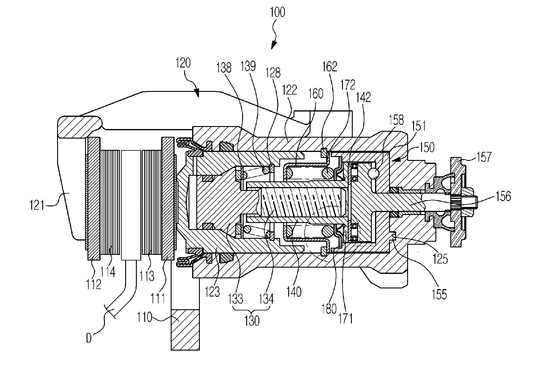
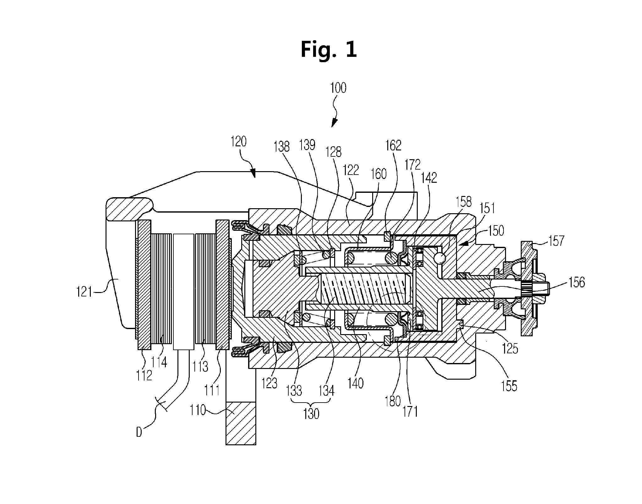
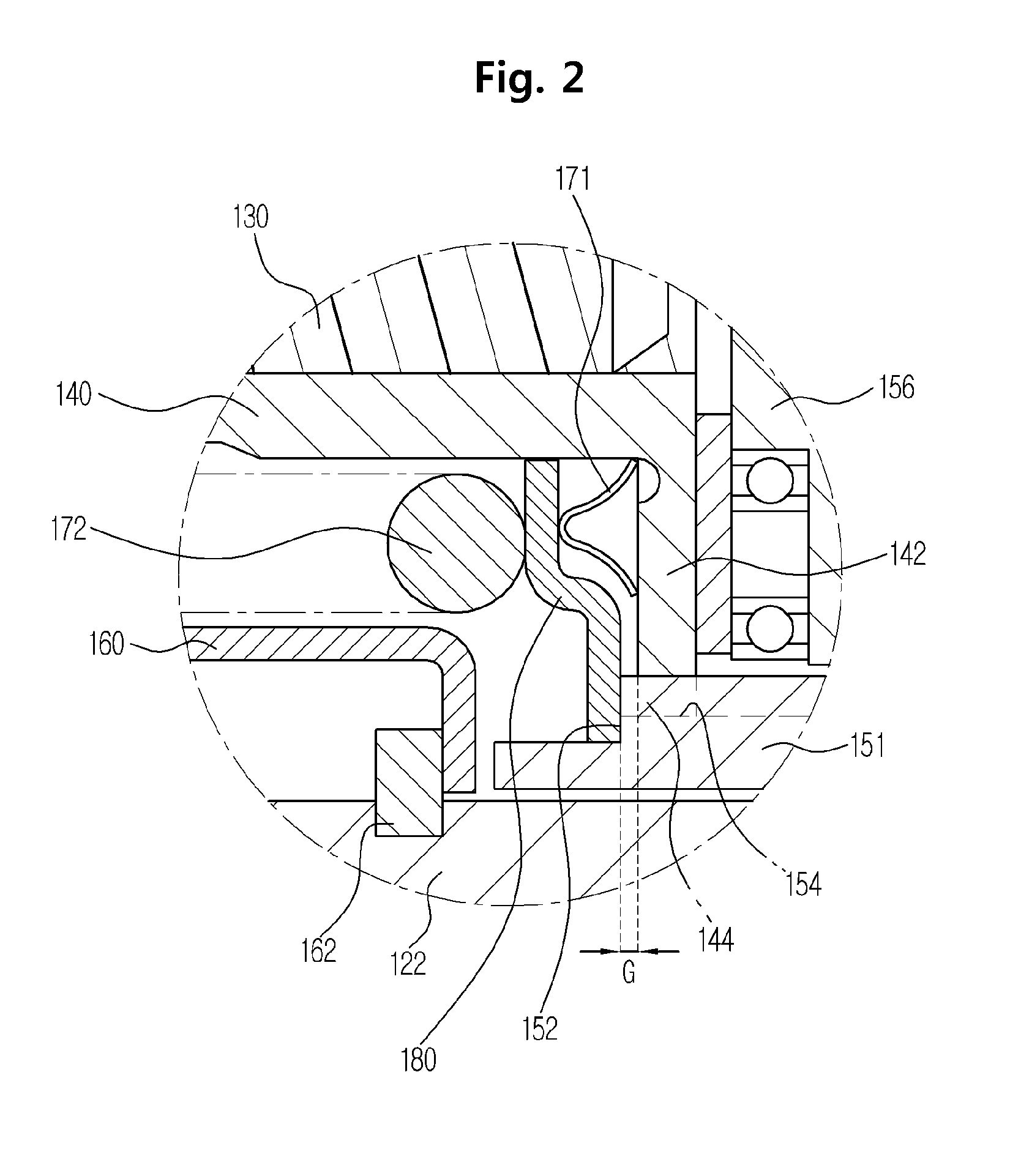
[0032]FIG. 1 is a cross sectional view illustrating a disc brake according to an embodiment of the present invention, FIG. 2 is an enlarged view illustrating a gap formed between a push rod and a support plate provided in the disc brake disc brake acco...


PUM


Abstract

Disclosed is a disc brake including a carrier on which a pair of pad plates are movably installed and a caliper housing, which is slidably installed on the carrier and is provided with a cylinder having a piston mounted so as to move forward and backward by a hydraulic braking pressure, the disc brake including: an adjuster installed in the piston to prevent the pad plates from moving away from a disc and to maintain the pad plates at a constant distance from the disc; a push rod installed in the cylinder, a front portion thereof being screw-coupled to the adjuster and a rear portion thereof being provided with a flange extending toward an inner circumferential surface of the cylinder; a ramp unit into which the rear portion of the push rod is inserted and which is installed in the cylinder and compresses the push rod toward the piston in cooperation with a parking cable to prevent rotation of the push rod; a spring case having an end portion of one side thereof fixed to the cylinder and forming a predetermined accommodation space between the inner circumferential surface of the cylinder and the push rod; a first elastic member and a second elastic member arranged in series with each other in the accommodation space of the spring case to provide elastic force to the push rod; and a support plate supported by an end portion of the ramp unit and interposed between the first elastic member and the second elastic member.

Description

CROSS-REFERENCE TO RELATED APPLICATIONS[0001]This application claims the benefit of Korean Patent Application No. 2013-0100786, filed on Aug. 26, 2013 in the Korean Intellectual Property Office, the disclosure of which is incorporated herein by reference.BACKGROUND[0002]1. Field[0003]Embodiments of the present invention relate to a disc brake, and more particularly, to a disc brake capable of stably returning a piston after a braking operation is terminated while improving the effect of return of a piston.[0004]2. Description of the Related Art[0005]A disc brake is an apparatus for braking a vehicle by forcedly causing friction pads to be pressed against both sides of a disc that rotates together with a wheel of the vehicle to stop the disc rotating. In the disc brake, a parking brake configured to keep a vehicle stationary is used at the time of parking.[0006]In general, a disc brake includes one pair of pad plates disposed at both sides of a disc that rotates with a wheel of a veh...

Claims


Application Information

Patent Timeline
Patent Type & Authority Applications(United States)
IPC IPC(8): F16D65/54
CPCF16D65/543F16D65/567F16D65/56
Inventor HONG, SEON-KIKONG, YOUNG-HUN
Owner HL MANDO CORP
Why Eureka
Try Eureka