Developing assembly, process cartridge, and image-forming apparatus

a technology of developing assembly and process cartridge, which is applied in the direction of electrographic process apparatus, instruments, optics, etc., can solve the problems of difficult to adjust the thickness of the toner layer, short life of the developing assembly, and melting of the toner and adhesion to the developing roller, etc., to achieve the effect of better image formation

Active Publication Date: 2015-02-26
CANON KK
View PDF1 Cites 7 Cited by
  • Summary
  • Abstract
  • Description
  • Claims
  • Application Information

AI Technical Summary

Benefits of technology

[0007]It is an object of the present invention to provide a technique that allows better image formation in an image-forming apparatus.

Problems solved by technology

In the configuration of the prior art, toner borne by the dielectric portion strongly adheres to the dielectric portion electrostatically, therefore regulating the toner layer thickness is difficult, and the toner coating amount on the developing roller, when the solid white image is formed, becomes higher compared with the case of forming a solid image.
Further, the developer regulating member has only the function to adjust the coating amount, and has no scraping off function, hence if a low printing page is continuously outputted, toner may melt and adhere to the developing roller.
To avoid these image defects due to the melt adhesion of toner, the life of the developing assembly in some cases may be set to be short.

Method used


Image

  • Developing assembly, process cartridge, and image-forming apparatus
  • Developing assembly, process cartridge, and image-forming apparatus
  • Developing assembly, process cartridge, and image-forming apparatus

Examples


example 1

Image-Forming Apparatus

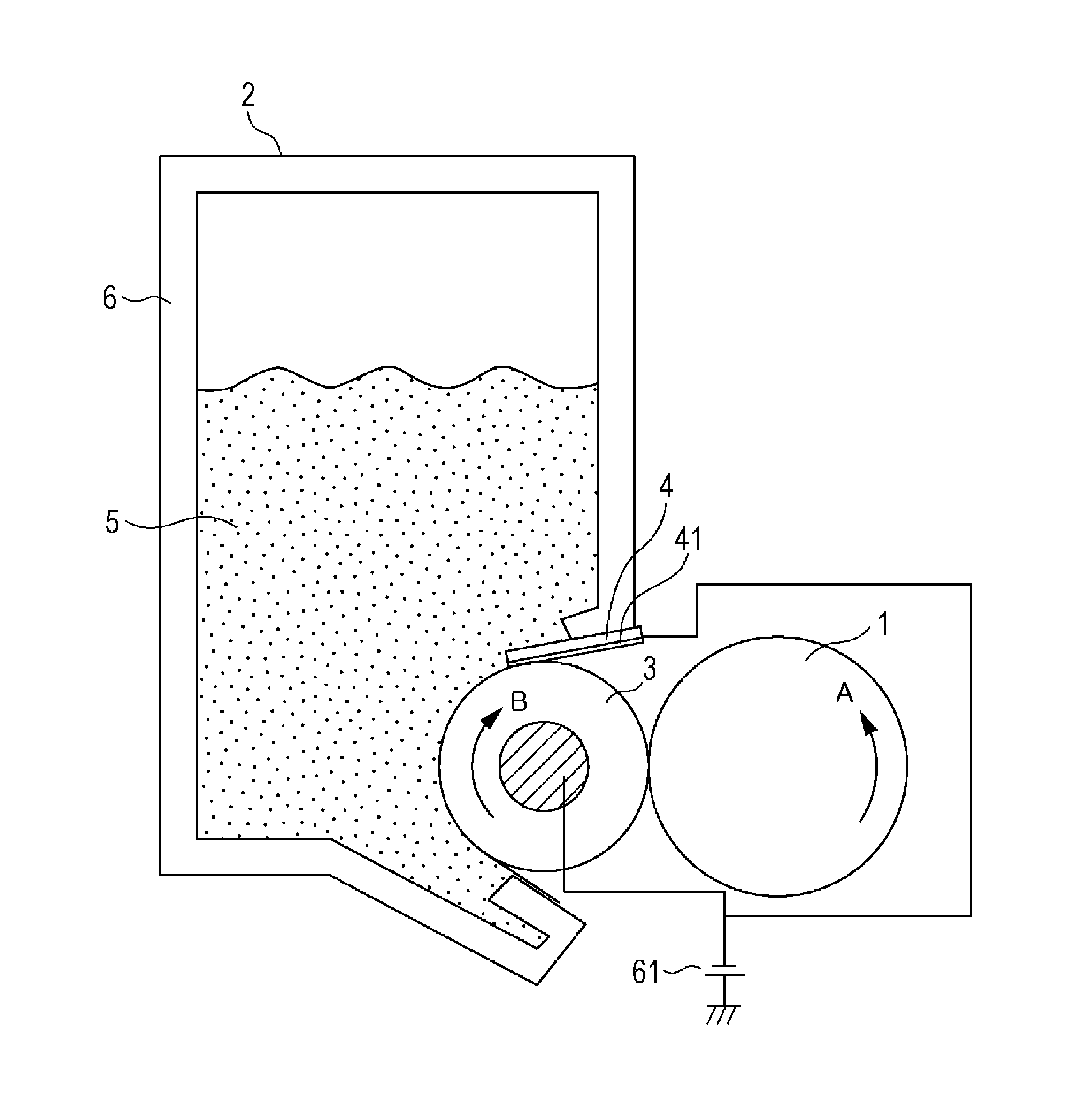
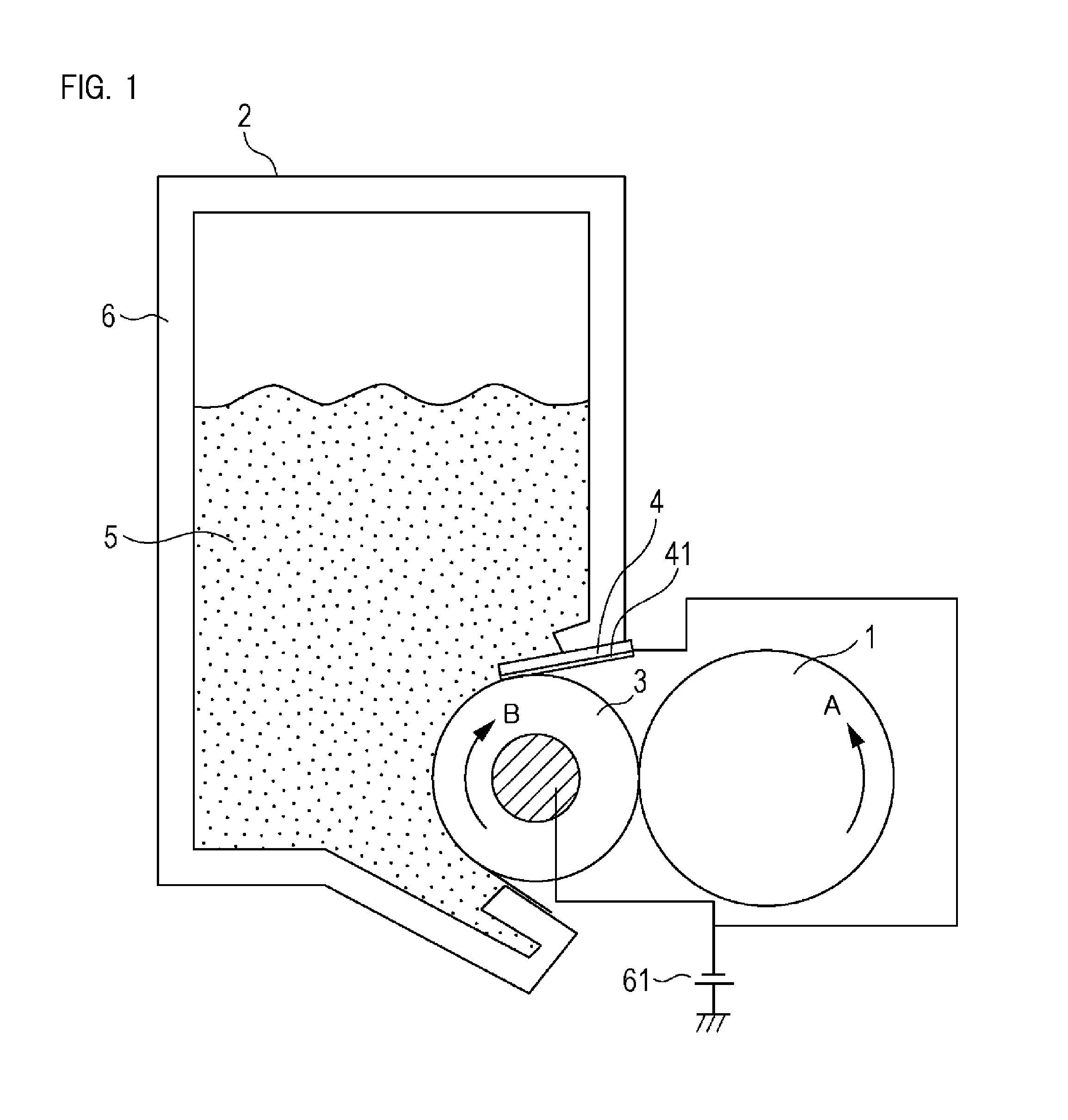
[0038]FIG. 13 shows a general configuration of an image-forming apparatus 100 according to an example of the present invention. Here the image-forming apparatus (electrophotographic image-forming apparatus) is for forming an image on a recording material (recording medium) by developer (toner) using the electrophotographic image forming process. For example, [the image-forming apparatus] includes an electrophotographic copier, an electrophotographic printer (e.g. an LED printer, a laser beam printer), an electrophotographic facsimile device, an electrophotographic word processor, and a composite machine thereof (multifunction printer). The recording material is a recording medium on which an image is formed, such as recording paper, an OHP sheet, a plastic sheet and cloth. As a major configuration, the image-forming apparatus 100 of this example includes a photosensitive drum 1, a developing assembly 2, a cleaning apparatus 8, a charging roller 7, an exposure ...

example 2

[0075]An image-forming apparatus according to Example 2 of the present invention will be described with reference to FIG. 11 and FIG. 12. Here only the differences from Example 1 will be described, and a same composing element as Example 1 is denoted with a same reference symbol, for which description is omitted. Matters not described here are the same as Example 1.

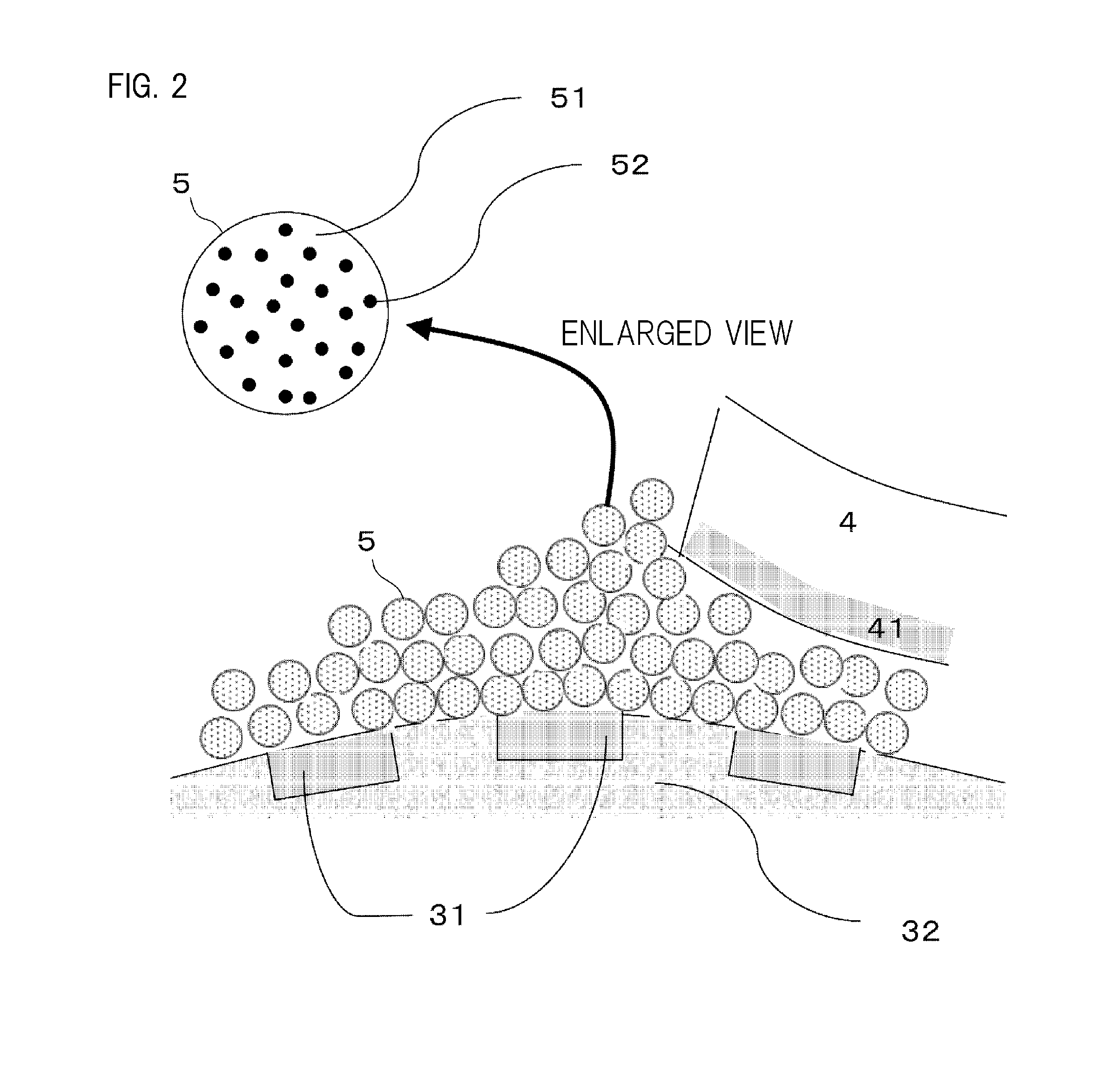
[0076]Unlike the developing assembly 2 of Example 1, the image-forming apparatus according to this example has no charging layer 41 of the metal blade 4, so that toner coating amount on the surface of the developing roller 3 is controlled by applying the blade bias on the metal blade 4, as illustrated in FIG. 11.

[0077]In this example, the electric field where toner is scraped off from the high resistance dielectric portion 31 and the intermediate resistance dielectric portion 32 is formed by the blade bias, hence the potential of each dielectric portion during image formation must be accurately detected. The potential of ...


PUM

PropertyMeasurementUnit
circumferential velocityaaaaaaaaaa
outer diameteraaaaaaaaaa

Abstract

First and second dielectric portions and colored particles have − polarity, and a regulating portion and an externally added particles have + polarity; concerning triboelectric series, (−)<second dielectric portion<first dielectric portion<regulating portion (+) and (−) colored particles<second dielectric portion<first dielectric portion<externally added particles (+); and concerning work functions, the difference between the colored particles and the second dielectric portion<the difference between the second dielectric portion and the externally added particles, the difference between the colored particles and the first dielectric portion<the difference between the first dielectric portion and the externally added particles, and the difference between the colored particles and the regulating portion>the difference between the regulating portion and the externally added particles.

Description

BACKGROUND OF THE INVENTION[0001]1. Field of the Invention[0002]The present invention relates to a developing assembly that is used for an image-forming apparatus based on an electrophotographic system.[0003]2. Description of the Related Art[0004]A developing assembly, that does not include a developer supply member, has been proposed to downsize and reduce cost of a developing assembly. The developer supply member has a function to supply and scrape off developer (hereafter called “toner”) to / from a developing roller (developer bearing member), and is installed mainly for handling a ghost and a solid image follow-up failure. A ghost is a phenomenon that appears when a half tone image is formed after a high density solid image is formed, where the traces of the solid image appear on the half tone image. A solid image follow-up failure is a phenomenon that appears when a 100% solid image is drawn on the entire surface of an image, where the density of the rear end of the image decrea...

Claims


Application Information

Patent Timeline
Patent Type & Authority Applications(United States)
IPC IPC(8): G03G15/08
CPCG03G2221/163G03G15/081G03G15/0818G03G15/0812
Inventor GOTO, GOSUKEKOYANAGI, MASATOISHIDA, KAZUTOSHI
Owner CANON KK
Why Eureka
Try Eureka