Wheel rim equipped with an inflation valve and method of installation of such a valve

Active Publication Date: 2015-03-05
CONTINENTAL AUTOMOTIVE FRANCE +1
View PDF2 Cites 6 Cited by
  • Summary
  • Abstract
  • Description
  • Claims
  • Application Information

AI Technical Summary

Benefits of technology

[0010]The object of the present invention is to overcome the disadvantages mentioned above by creating an inflation valve capable of elastic deformation that is capable of being installed on wheel rims having a thickness of less than 1.5 mm without any reduction in the service life of such valves and without any

Problems solved by technology

This results in risks of shear ruptures (cutting) of the elastic material at the bottom of the sealing groove, leading in the long term to air leakage and a lack of sealing of the inflation valve.
The in

Method used


Image

  • Wheel rim equipped with an inflation valve and method of installation of such a valve
  • Wheel rim equipped with an inflation valve and method of installation of such a valve
  • Wheel rim equipped with an inflation valve and method of installation of such a valve

Examples


Embodiment Construction

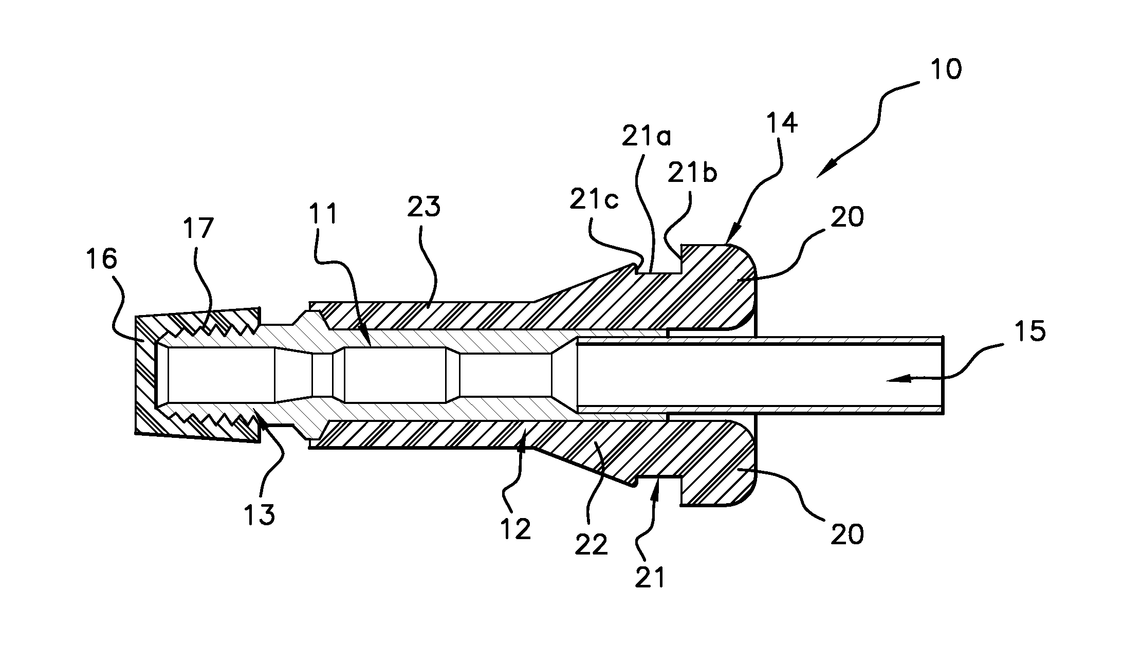
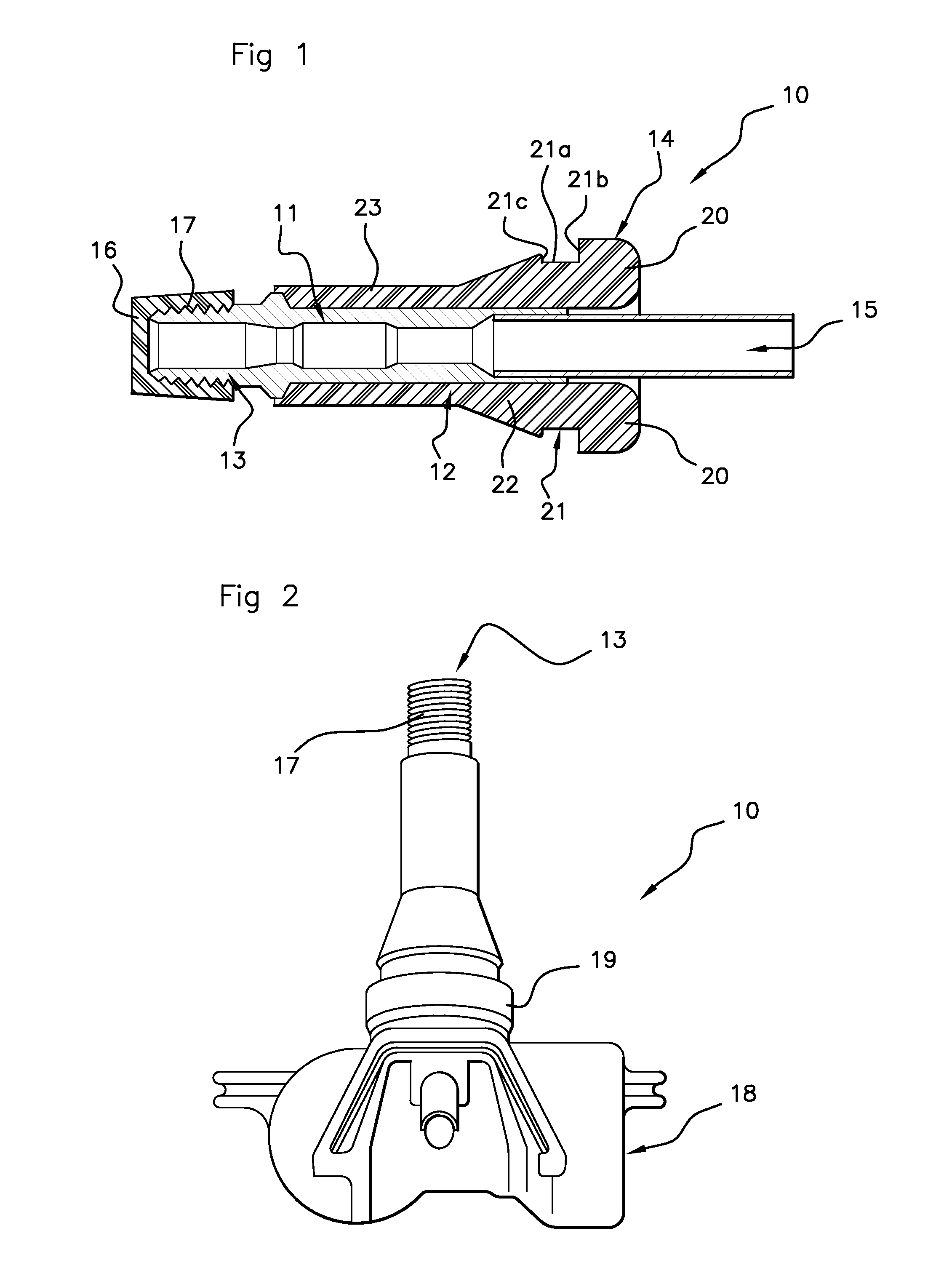
[0038]The inflation valves 10 that are capable of elastic deformation of a known type usually consist (FIG. 1):[0039]of a metal valve core 11,[0040]of a valve body 12 made from an elastically deformable material at least partially covering the valve core 11.

[0041]The inflation valve formed in this way includes an external extremity 13 for receiving a cap 16 screwed onto a thread 17 for the purpose of blocking an air passageway 15 in a detachable manner, and an internal extremity 14 constituting a valve head 20. The air passageway 15 discharges at the level of the internal extremity 14 of the valve.

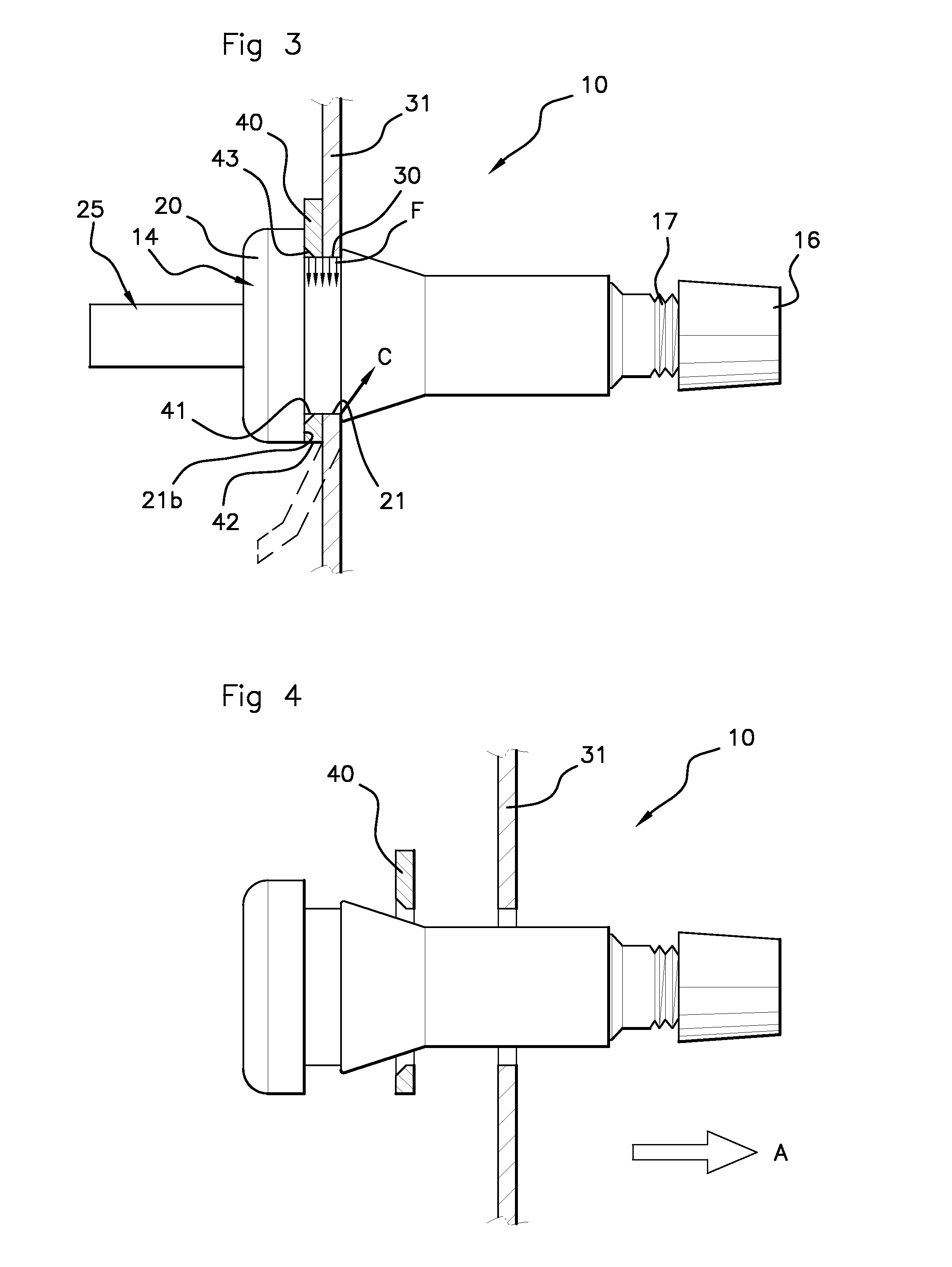
[0042]In a known manner, the valve body includes:[0043]a valve head 20 (FIG. 3) situated at the level of the internal extremity 14 of the valve and exhibiting a diameter greater than that of an opening 30 in a wheel rim 31 intended to receive the inflation valve,[0044]a sealing groove 21 (FIG. 1) exhibiting essentially a U-shaped form, that is to say, having a bottom 21a that is essentiall...


PUM


Abstract

A wheel rim is equipped with an inflation valve (10) that is capable of elastic deformation adapted to be positioned in an opening (30) in the wheel rim (31) of a wheel of a motor vehicle. The valve (10) exhibits a valve body (12) made from an elastically deformable material surrounding a valve core (11) adapted to form an air passageway (15). The valve body (12) is provided with a sealing groove (21) adapted to receive the wheel rim, and with an intermediate part (22) having a diameter greater than the opening in the wheel rim. The inflation valve (10) is provided in addition with an element for the distribution (40) of shear forces pre-installed on the valve body (12). A method of installation of the inflation valve is also described.

Description

FIELD OF THE INVENTION[0001]The present invention relates to a motor vehicle wheel rim equipped with an inflation valve and a method of installation of such a valve. More specifically, it relates to a wheel rim equipped with an inflation valve that is capable of elastic deformation (inflation valve referred to as “snap-in” type in English language) adapted to be positioned in an opening in the wheel rim. This valve may be associated with an electronic tire pressure monitoring module. The invention also relates to an inflation valve and a method of installation of an inflation valve on a wheel rim.BACKGROUND OF THE INVENTION[0002]It is, in fact, already well known to monitor pressure that is present in the interior of the tires of a motor vehicle. For this purpose, the monitoring systems known to date include, for example:[0003]at the level of at least one wheel of the vehicle, a wheel module including an electronic module associated with an inflation valve of the tire and,[0004]at t...

Claims


Application Information

Patent Timeline
IPC IPC(8): B60C29/00
CPCB60C29/005B60C23/0494B60C29/02Y10T137/0491Y10T137/374
Inventor LELIEVRE, GWENNGAUGAIN, FREDERICPETITJEAN, PASCAL
Owner CONTINENTAL AUTOMOTIVE FRANCE
Why Eureka
Try Eureka