Torque split gearbox for rotary wing aircraft

Active Publication Date: 2015-03-05
SIKORSKY AIRCRAFT CORP
View PDF13 Cites 33 Cited by
  • Summary
  • Abstract
  • Description
  • Claims
  • Application Information

AI Technical Summary

Benefits of technology

[0005]In another embodiment, a drive system for a dual coaxial counter rotating assembly includes an engine outputting a first torque via an input shaft and a gearbox assembly to reduce the first torque to a second torque and transfer the second torque to the dual coaxial counter rotating assembly. The gearbox assembly includes an input bevel shaft operably connected to the input shaft to transfer the first torque therethrough and two gear sets operably connected to the

Problems solved by technology

In other rotary wing aircraft with more complex rotor systems, the complexity of the gearbox typ

Method used


Image

  • Torque split gearbox for rotary wing aircraft
  • Torque split gearbox for rotary wing aircraft
  • Torque split gearbox for rotary wing aircraft

Examples


Embodiment Construction

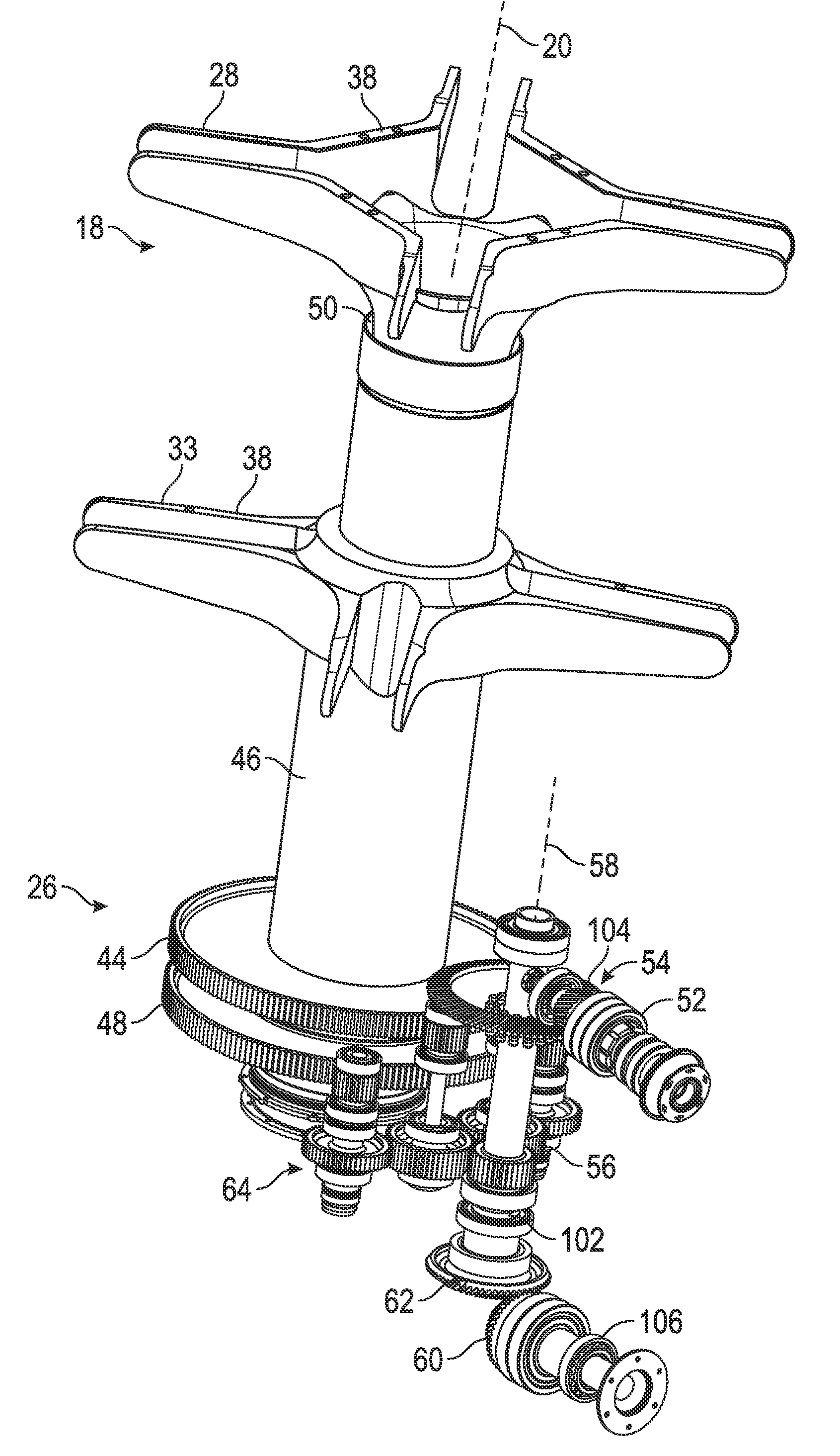
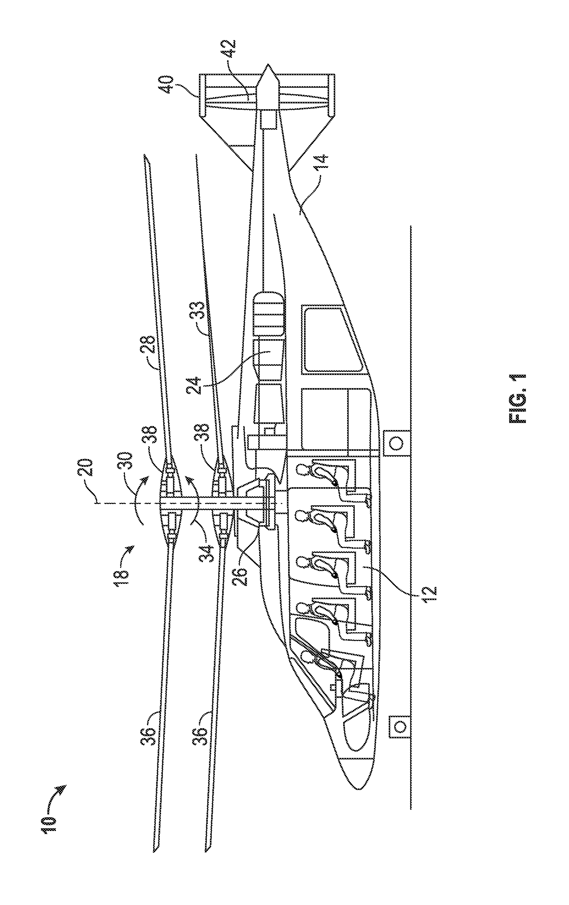
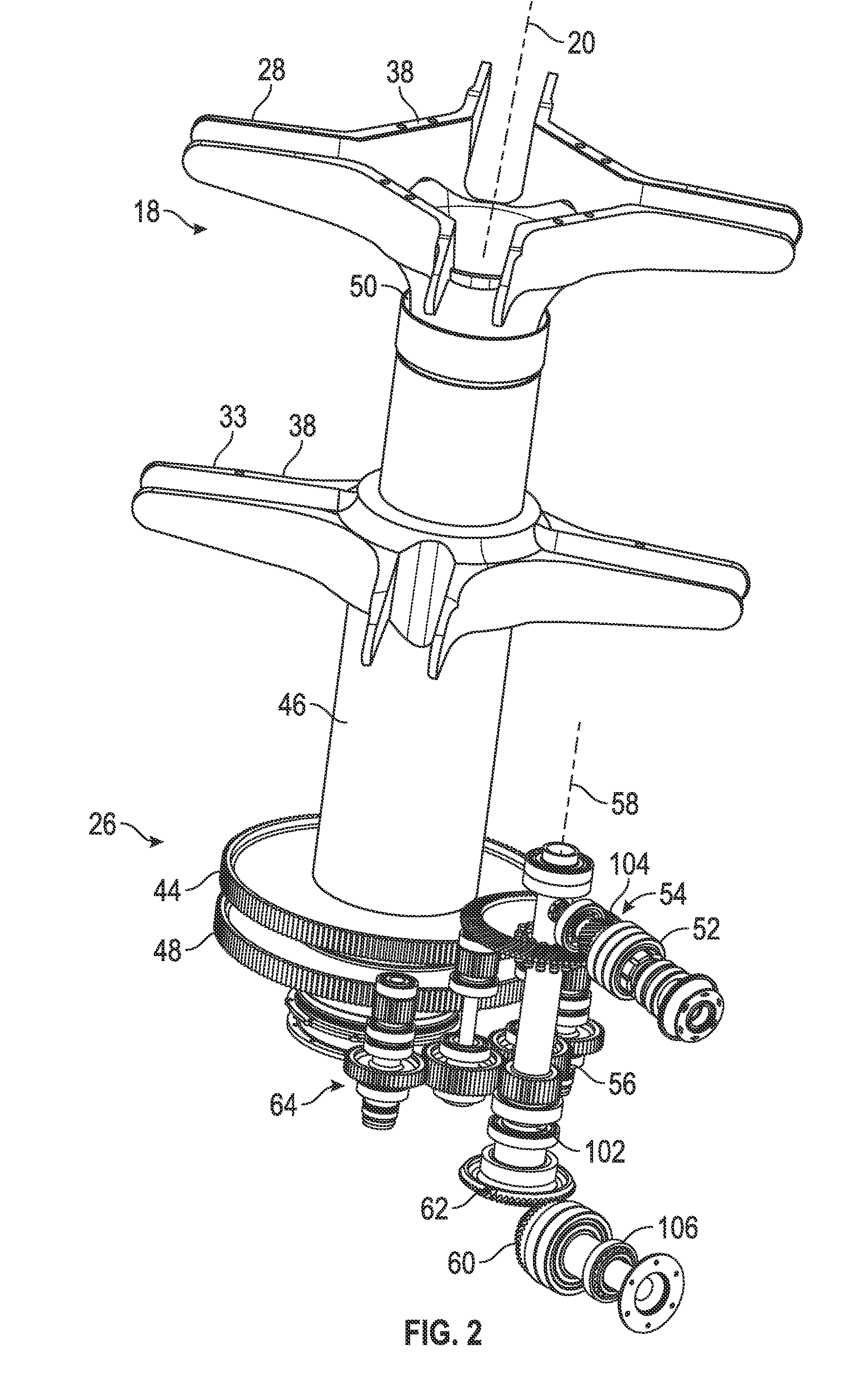
[0015]Shown in FIG. 1 is schematic view of an embodiment of a rotary wing aircraft, in this embodiment a helicopter 10. The helicopter 10 includes an airframe 12 with an extending tail 14. A dual, counter rotating coaxial main rotor assembly 18 is located at the airframe 12 and rotates about a main rotor axis 20. The main rotor assembly 18 is driven by a power source, for example, an engine 24 via a gearbox 26. The main rotor assembly 18 includes an upper rotor assembly 28 driven in a first direction 30 about the main rotor axis 20, and a lower rotor assembly 32 driven in a second direction 34 about the main rotor axis 20, opposite to the first direction 30. While, in FIG. 1, the first direction 30 is illustrated as counter-clockwise and the second direction 34 is illustrated as counter clockwise, it is to be appreciated that in some embodiments the directions of rotation of the upper rotor assembly 28 and lower rotor assembly 32 may be reversed. Each of the upper rotor assembly 28 ...


PUM


Abstract

A gearbox system for a dual coaxial counter rotating rotor assembly includes an input shaft to input a first torque into the gearbox system and a transfer shaft operably connected to the input shaft to transfer the first torque therethrough. Two gear sets are operably connected to the transfer shaft. Each gear set includes a first output gear to transfer a second torque acting in a first direction to a first rotor of a rotor assembly and a second output gear to transfer the second torque acting in a second direction opposite the first direction to a second rotor of the rotor assembly. The second torque transferred by each gear set of the two gear sets is substantially equal.

Description

BACKGROUND[0001]The subject matter disclosed herein relates to the art of rotary wing aircraft and, more specifically, to gearbox systems for rotary wing aircraft.[0002]A gearbox system of a rotary wing aircraft transfers power from an engine, or multiple engines, for example, a turbine engine, to the rotor system. A typical system directs power from the engine to a single rotor system including a plurality of rotor blades. Since rotational velocity of the rotor is typically lower than the rotational velocity of the engine, the gearbox is used to reduce the rotational velocity of the turbine engine. Torque is subsequently increased through a series of intermediate gear stages and shafts, with an output velocity provided to the rotor system.[0003]In other rotary wing aircraft with more complex rotor systems, the complexity of the gearbox typically also increases. For example, some rotary wing aircraft, such as the X2® helicopter produced by Sikorsky Aircraft Corporation, have two coa...

Claims


Application Information

Patent Timeline
IPC IPC(8): B64D35/06B64C27/10
CPCB64C27/10B64D35/06B64C27/12F16H37/065Y10T74/19121
Inventor GARCIA, TODD A.
Owner SIKORSKY AIRCRAFT CORP
Why Eureka
Try Eureka