Line printer and method for controlling the same

Active Publication Date: 2015-03-05
SEIKO EPSON CORP
View PDF1 Cites 10 Cited by
  • Summary
  • Abstract
  • Description
  • Claims
  • Application Information

AI Technical Summary

Benefits of technology

[0007]An advantage of some aspects of the invention is to inspect a liquid discharge state using residu

Problems solved by technology

There is a case in which thickened ink in the cavity causes discharge failure.
Since the method is a consequence management performed after the nozzle omission occurs, it is difficult to detect a symptom of the nozzle omission and to avoid image quality being deteriorated.
Therefore, if the method f

Method used


Image

  • Line printer and method for controlling the same
  • Line printer and method for controlling the same
  • Line printer and method for controlling the same

Examples


embodiment

A. Embodiment

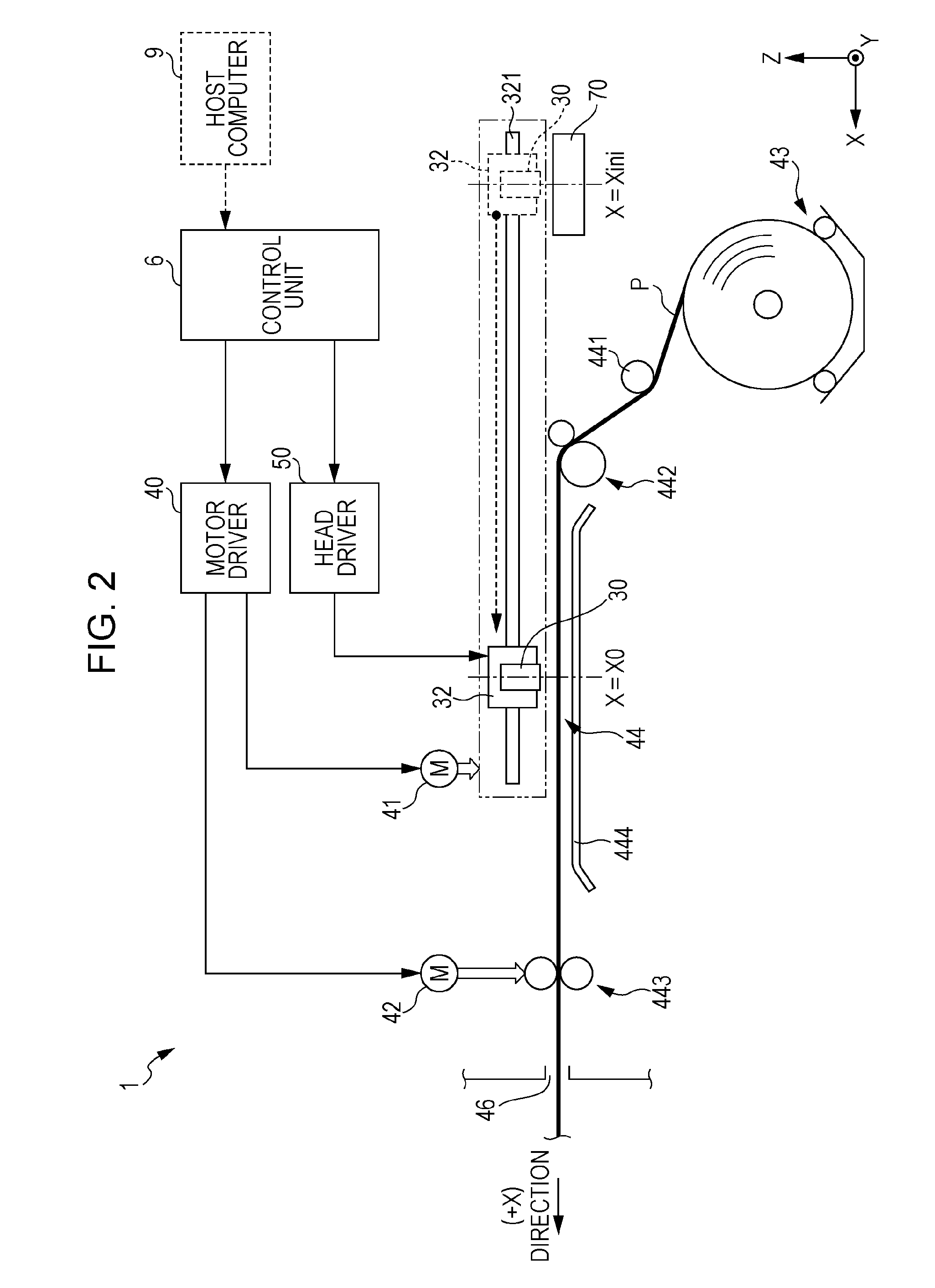
[0049]In this embodiment, an ink jet type line printer, which discharges ink (an example of “liquid”) and forms an image on a recording sheet P (an example of a “recording medium”), will be described as an example of a printing apparatus.

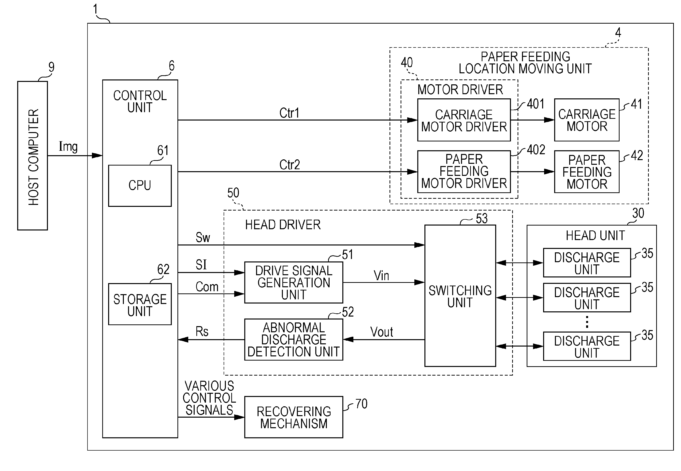
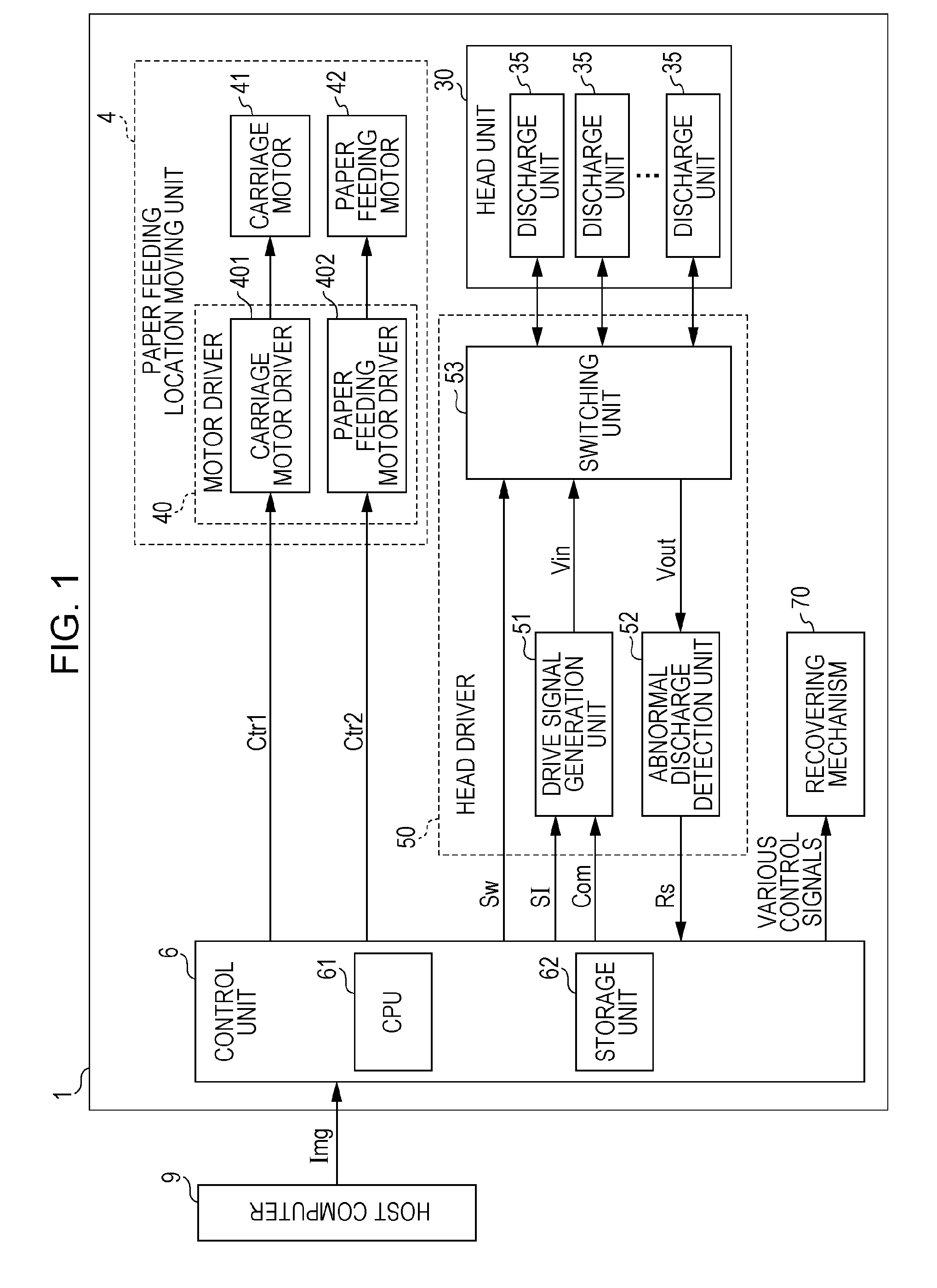
[0050]FIG. 1 is a functional block diagram illustrating the configuration of an ink jet printer 1 according to the embodiment. As shown in the drawing, the ink jet printer 1 includes a head unit 30 which includes M (M is a natural number which is equal to or greater than 2) discharge units 35 which are capable of discharging ink charged therein, a head driver 50 which drives the head unit 30, a paper feeding location moving unit 4 (an example of a “relative position movement unit”) which moves the relative position of the head unit 30 with regard to the recording sheet P, and a recovering mechanism 70 which performs a recovery process to recover a discharge state of the discharge unit 35 to a normal state when abnormal discharge is dete...

modification example

C. Modification Example

[0193]Each of the above embodiments may modified in various manners. Detailed modification aspects will be shown below. Two or more aspects which are arbitrarily selected from examples below may be appropriately merged with each other in a range in which they do not contradict each other.

first modification example

[0194]In the above-described embodiment, the inspection drive signal Vin includes three states of the first potential V1, the second potential V2 and the third potential V3. However, the invention is not limited thereto, and the inspection drive signal Vin may have a signal waveform which includes four or more potentials.

[0195]For example, as shown in FIG. 29, in a period from the termination time t1e of the first period T1 to the start time t2s of the second period T2, a fourth period T4 in which a fourth potential VA may be maintained is provided, a change is performed from the first potential V1 to the fourth potential VA from the time t1e to the time t4s, and a change is performed from the fourth potential VA to the second potential V2 from the time t4e to the time t2s.

[0196]Here, a potential difference ΔV42 between the fourth potential VA and the second potential V2 is greater than a potential difference ΔV12 between the first potential V1 and the second potential V2. According...


PUM


Abstract

There is provided a line printer including: a nozzle that discharges liquid; a pressure chamber that communicates with the nozzle; a piezoelectric element that is provided to correspond to the pressure chamber and to discharge liquid; a pulse generation unit that generates a drive pulse to discharge liquid from the nozzle and an inspection pulse to inspect a liquid discharge state; and a residual vibration detection unit that detects residual vibration in the pressure chamber, which occurs after the inspection pulse is applied to the piezoelectric element. The drive pulse is caused to be applied to the piezoelectric element and the inspection pulse is caused not to be applied to the piezoelectric element at a first printing speed. The drive pulse and the inspection pulse are caused to be applied to the piezoelectric element at a second printing speed. The second printing speed is slower than the first printing speed.

Description

BACKGROUND[0001]1. Technical Field[0002]The present invention relates to a line printer and a method for controlling the same.[0003]2. Related Art[0004]An ink jet type line printer performs printing by discharging ink from the inside of a cavity. If ink dries, the ink is thickened. There is a case in which thickened ink in the cavity causes discharge failure. If nozzle omission in which it is difficult to discharge ink from a nozzle occurs, white stripes are recorded on a recording sheet corresponding to the nozzle failure. Here, JPA-2008-284868 discloses a method for detecting nozzle omission by analyzing image data which is acquired by imaging an ink discharge state.[0005]Since the method is a consequence management performed after the nozzle omission occurs, it is difficult to detect a symptom of the nozzle omission and to avoid image quality being deteriorated. In order to solve the problem, there has been known a method for monitoring an ink discharge state before nozzle omissi...

Claims


Application Information

Patent Timeline
IPC IPC(8): B41J2/045
CPCB41J2/04581B41J2/04541B41J2/0451B41J2/14233B41J2/14274
Inventor OTOKITA, KENJI
Owner SEIKO EPSON CORP
Why Eureka
Try Eureka