

Method and apparatus for recognizing road shape
a road shape and recognition technology, applied in the field of road shape recognition, can solve the problems of significant reduction in recognition accuracy and inability to recognize road shapes, and achieve the effect of improving the recognition accuracy of road shape recognition
- Summary
- Abstract
- Description
- Claims
- Application Information
AI Technical Summary
Benefits of technology
Problems solved by technology
Method used
Image

Examples
first embodiment
[0030]A first embodiment of the present invention will hereinafter be described with reference to the drawings.
[0031]The present invention is not limited in interpretation in any way by the embodiment described below. An aspect in which a part of the embodiment described below has been omitted to an extent enabling the problems to be solved is also an embodiment of the present invention. In addition, any aspect conceivable without departing from the essence of the invention specified by only the expressions recited in the scope is also an embodiment of the present invention. In addition, reference numbers used in the description of the embodiment below are used accordingly in the scope of claims. However, the reference numbers are used for the purpose of facilitating understanding of the invention in each claim and are not intended to limit the technical scope of the invention in each claim.
[0032]
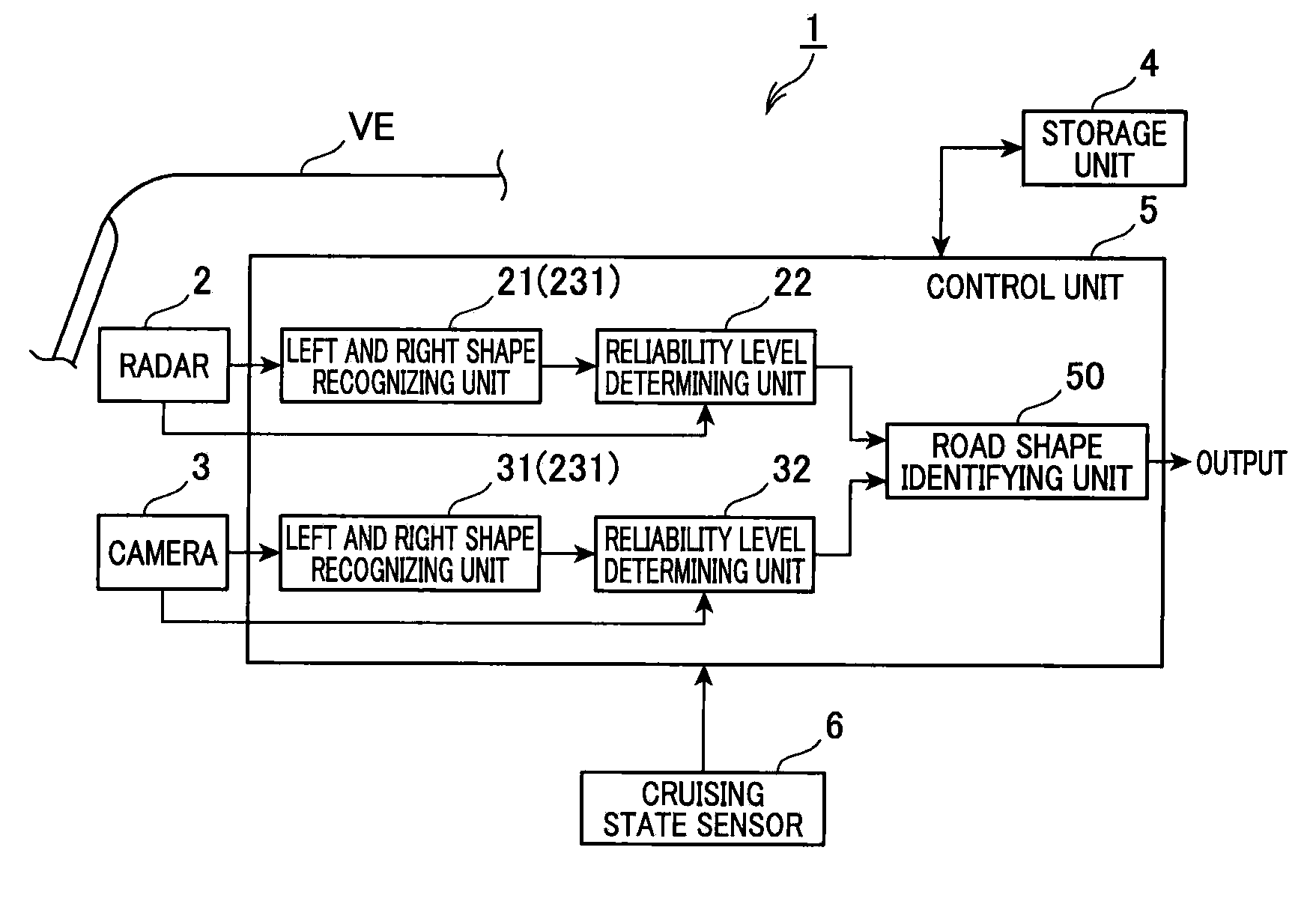
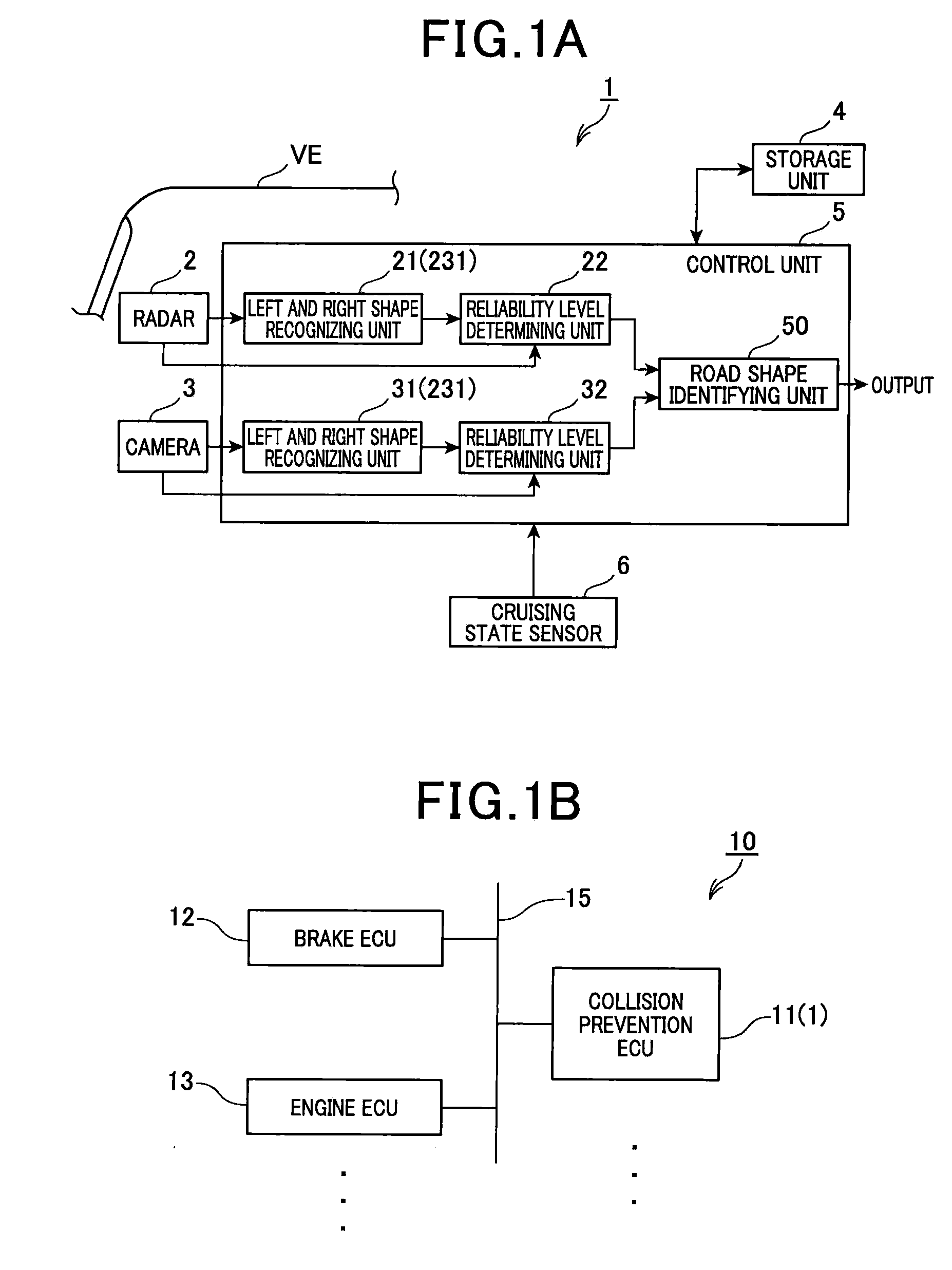
[0033]A road shape recognition apparatus 1 shown in FIG. 1A is mounted in a vehicle. Th...
application example
[0086]Next, an application example of the road shape recognition apparatus 1 will be described.
[0087]A vehicle control system 10 shown in FIG. 1B includes a collision prevention electronic control unit (ECU) 11, a brake ECU 12, and an engine ECU 13. The collision prevention ECU 11 includes the road shape recognition apparatus 1. The ECUs 11 to 13 are capable of communicating with one another over an on-board local area network (LAN) 15. The ECUs 11 to 13 transmit and receive various types of information and control commands to and from one another. As a result, the ECUs 11 to 13 are capable of sharing detection information from the sensors and actualizing vehicle control in cooperation with other ECUs.
[0088]The brake ECU 12 controls braking of the vehicle. The brake ECU 12 includes a CPU, a ROM, a RAM, and the like. Specifically, the brake ECU 12 controls a brake ACT based on detection values from a sensor that detects the depression amount of a brake pedal. The brake ACT is an actu...
second embodiment
[0098]Next, a second embodiment of the present invention will be described. The basic configuration according to the second embodiment is similar to that according to the first embodiment. Therefore, descriptions related to common configurations will be omitted. Differences will mainly be described.
[0099]According to the above-described first embodiment, the left and right shape recognizing unit 21 sends, to the road shape identifying unit 50, information indicating an aggregation of detection points (positional coordinates) of a roadside object as the road edge shape information. The left and right shape recognizing unit 31 sends, to the road shape identifying unit 50, information indicating an aggregation of detection points (positional coordinates) of a lane boundary line as the lane shape information.
[0100]The road shape identifying unit 50 then compares the positional coordinates indicated in the road edge shape information and the positional coordinates indicated in the lane s...
PUM
 Abstract
Description
Claims
Application Information