Turbine blade and associated method for producing a turbine blade

Inactive Publication Date: 2015-03-05
SIEMENS AG
View PDF27 Cites 6 Cited by
  • Summary
  • Abstract
  • Description
  • Claims
  • Application Information

AI Technical Summary

Benefits of technology

[0026]So that the turbine blade, with the inner platform part and the outer platform part in the form of the continuous platform frame surrounding the inner platform part, can be used even in high-te

Problems solved by technology

These oxidation problems arise, in particular, when the heat insulation layer often also provided there flakes off locally.
Such consequences may lead in the turbine blade to a

Method used


Image

  • Turbine blade and associated method for producing a turbine blade
  • Turbine blade and associated method for producing a turbine blade
  • Turbine blade and associated method for producing a turbine blade

Examples


Embodiment Construction

[0032]Identical features are given identical reference numerals in all the figures.

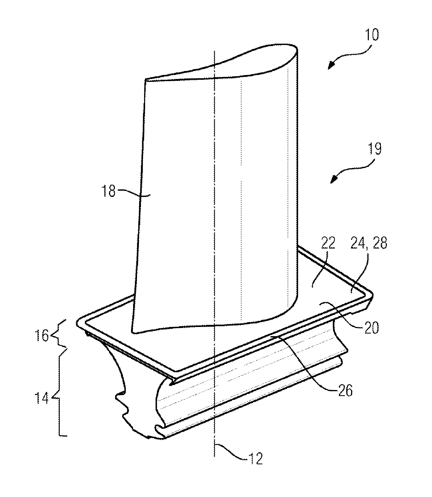
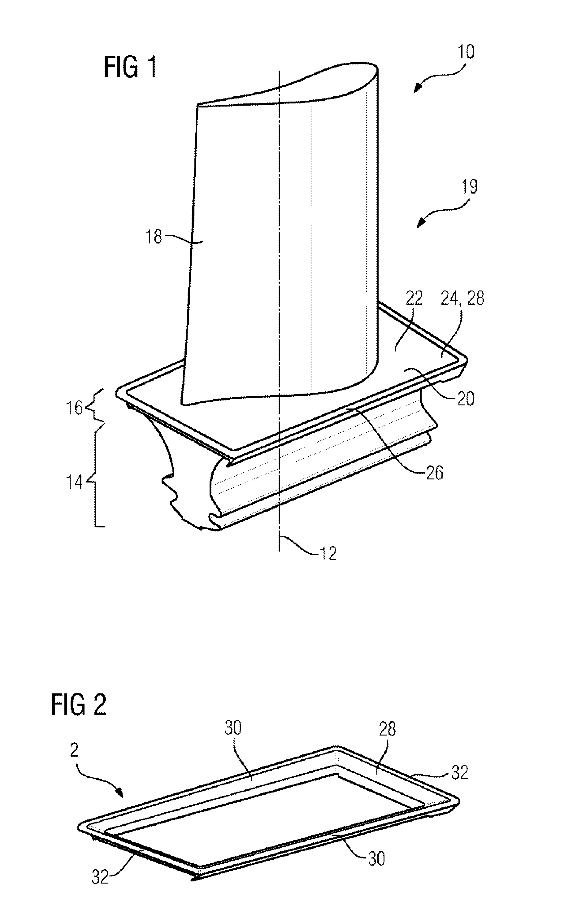
[0033]FIG. 1 shows a perspective illustration of a turbine blade 10. The turbine blade 10 is designed as a moving blade. However, it may also be designed as a guide blade. The turbine blade 10 comprises, succeeding one another directly along its longitudinal axis 12, a fastening portion 14, a platform 16 and a blade airfoil 18. The fastening portion 14 is contoured in a manner of a pine tree profile in a way typical of a moving blade. Guide blades for turbines mostly have, instead of the pine tree-shaped fastening portion 14, a plurality of hooks which are pushed into a guide blade carrier, not illustrated in any more detail, of the turbomachine.

[0034]The fastening portion 14 merges into the platform 16. According to the illustration chosen in FIG. 1, the platform 16 has an upwardly pointing platform surface 20 on which the blade airfoil 18 is seated. In the exemplary embodiment illustrated, the platf...


PUM

PropertyMeasurementUnit
Angleaaaaaaaaaa
Angleaaaaaaaaaa
Angleaaaaaaaaaa

Abstract

A turbine blade is provided, having a fastening section, a platform, and a blade, which follow one another along a longitudinal axis of the turbine blade, wherein the platform, in radial relation to the longitudinal axis, has an inner platform part and an outer platform part, wherein the outer platform part is designed as a closed platform frame that encloses the outer edge of the inner platform part. An associated method for producing a turbine blade is also provided.

Description

CROSS REFERENCE TO RELATED APPLICATIONS[0001]This application is the US National Stage of International Application No. PCT / EP2013 / 056594 filed Mar. 27, 2013, and claims the benefit thereof. The International Application claims the benefit of European Application No. EP12162103 filed Mar. 29, 2012. All of the applications are incorporated by reference herein in their entirety.FIELD OF INVENTION[0002]The invention relates to a turbine blade with a fastening portion, with a platform for delimiting a flow duct and with a blade airfoil, which succeed one another along a longitudinal axis of the turbine blade. The invention relates, furthermore, to a method for producing a turbine blade, comprising the step: production of a monolithic trunk blade comprising a blade airfoil, a platform for delimiting a flow duct and a fastening portion.BACKGROUND OF INVENTION[0003]Turbine blades and methods for producing turbine blades are known in many different forms from the abundant prior art. For exa...

Claims


Application Information

Patent Timeline
IPC IPC(8): F01D5/18F01D5/28
CPCF01D5/28F01D5/18F01D5/147F05D2240/80F01D11/008Y10T29/49339
Inventor AHMAD, FATHIBOLMS, HANS-THOMASKURT, NIHAL
Owner SIEMENS AG
Why Eureka
Try Eureka