Method for manufacturing optical fiber

a manufacturing method and technology of optical fiber, applied in the field of optical fiber preform drawing, can solve the problems of insufficient the cooling capacity of the cooling device declines, and the cooling of the bare optical fiber within the cooling device is insufficient, so as to reduce the mixing of bubbles into the protective covering layer, the adjustment of the cooling capacity can be appropriately adjusted, and the effect of increasing the concentration of carbon dioxide gas

Active Publication Date: 2011-11-10
THE FUJIKURA CABLE WORKS LTD
View PDF1 Cites 25 Cited by
  • Summary
  • Abstract
  • Description
  • Claims
  • Application Information

AI Technical Summary

Benefits of technology

[0037]In the method for manufacturing an optical fiber described in the above (1), the flow of the cooling gas within the cooling device is made to be an upward flow, and the cooling gas is discharged to outside from the upper end of the cooling device, by connecting the cooling device and the coating device in an airtight manner, and closing the flow of the cooling gas which flows toward the coating device side within the cooling device using the resin within the coating device. That is, the flow of the mixed gas of the helium gas and the carbon dioxide gas is made to be an upward flow which is stable toward the upper portion of the cooling device from the lower portion thereof. Thereby, the external gas which enters the cooling device from the upper portion of the cooling device along with the bare optical fiber can be reduced to a limit, and the concentration of the helium gas within the cooling device is increased.
[0038]Additionally, in the method for manufacturing an optical fiber described in the above (1), the temperature of the mixed gas is increased toward the upper portion of the cooling device from the introduction port for the cooling gas by adjusting the flow rate of the helium gas and the flow rate of the carbon dioxide gas. Thereby, since the transfer of the heat from the bare optical fiber to the cooling gas can be made to be gentle in the upper portion of the cooling device, the responsiveness of adjustment of the cooling capacity can be appropriately performed. In addition, since the cooling capacity can be adjusted to a stable range for manufacture, the bare optical fiber can be introduced into the coating device in a state where the temperature of the bare optical fiber forcibly cooled in the cooling device is uniform, the influence of the above disturbances is suppressed, and the diameter of the protective covering layer formed on the bare optical fiber can be made uniform.
[0039]In the method for manufacturing an optical fiber described in the above (6), the space filled with the carbon dioxide gas is formed on the lower portion side which is lower than the position where the helium gas is introduced. Thereby, since sufficient carbon dioxide gas exists in the vicinity of the coating resin in the coating device, bubbles can be prevented from being mixed into the protective covering layer.
[0040]According to the method for manufacturing an optical fiber described in the above (7), the concentration of the carbon dioxide gas can be increased by separating the space. As a result, the mixing of bubbles into the protective covering layer can be prevented.
[0041]According to the method for manufacturing an optical fiber described in the above (10), since the mixture of the helium gas and the carbon dioxide gas becomes uniform, the temperature of the mixed gas can be controlled with excellent reproducibility, and stability of the cooling capacity of the cooling device can be made very high.

Problems solved by technology

From the above, the concentration of the cooling gas within the cooling device decreases with the speeding up in the drawing speed, and the cooling capacity of the cooling device declines.
As a result, there is a case where cooling of the bare optical fiber within the cooling device becomes insufficient, and the external diameter (hereinafter referred to as coating diameter) of the protective covering layer becomes small, or there is a case where cooling of the bare optical fiber becomes unstable, and a fluctuation in the coating diameter increases.
However, within the drawing speed range, it may be considered that the influence that these changes have on the fluctuation in the coating diameter is small, and is almost non-existent.
However, the technique described in Patent Literature 1 has a problem that the cooling capacity of the cooling device 211 improves excessively, and the responsiveness of the cooling capacity to a change in the flow rate of the cooling gas becomes too agile.
Since the responsiveness of the cooling capacity of the cooling device 211 is too agile in the technique described in Patent Literature 1, a problem occurs in that the cooling capacity of the cooling device 211 becomes unstable due to the flow of the non-uniform cooling gas generated by this disturbance.
Therefore, it is difficult to keep the coating diameter constant by a feedback control (for example, PID control) of a constant value.
On the other hand, if PID setting values which make feedback control insensitive are used, the coating diameter cannot be kept constant.
As a result, there is a problem in that the coating diameter fluctuation increases and the percentage of defective manufactured optical fibers increases.

Method used


Image

  • Method for manufacturing optical fiber
  • Method for manufacturing optical fiber
  • Method for manufacturing optical fiber

Examples


example 1

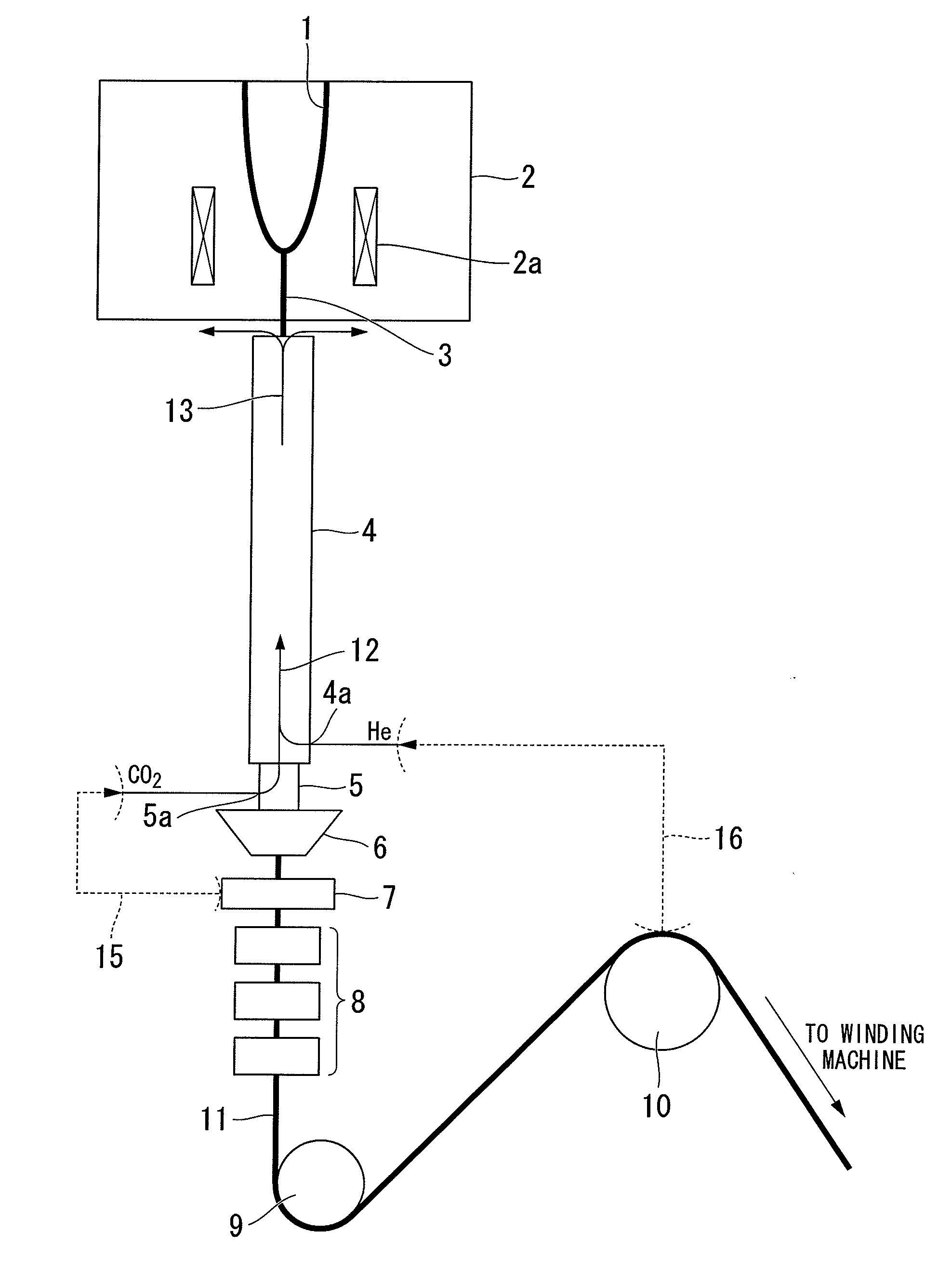
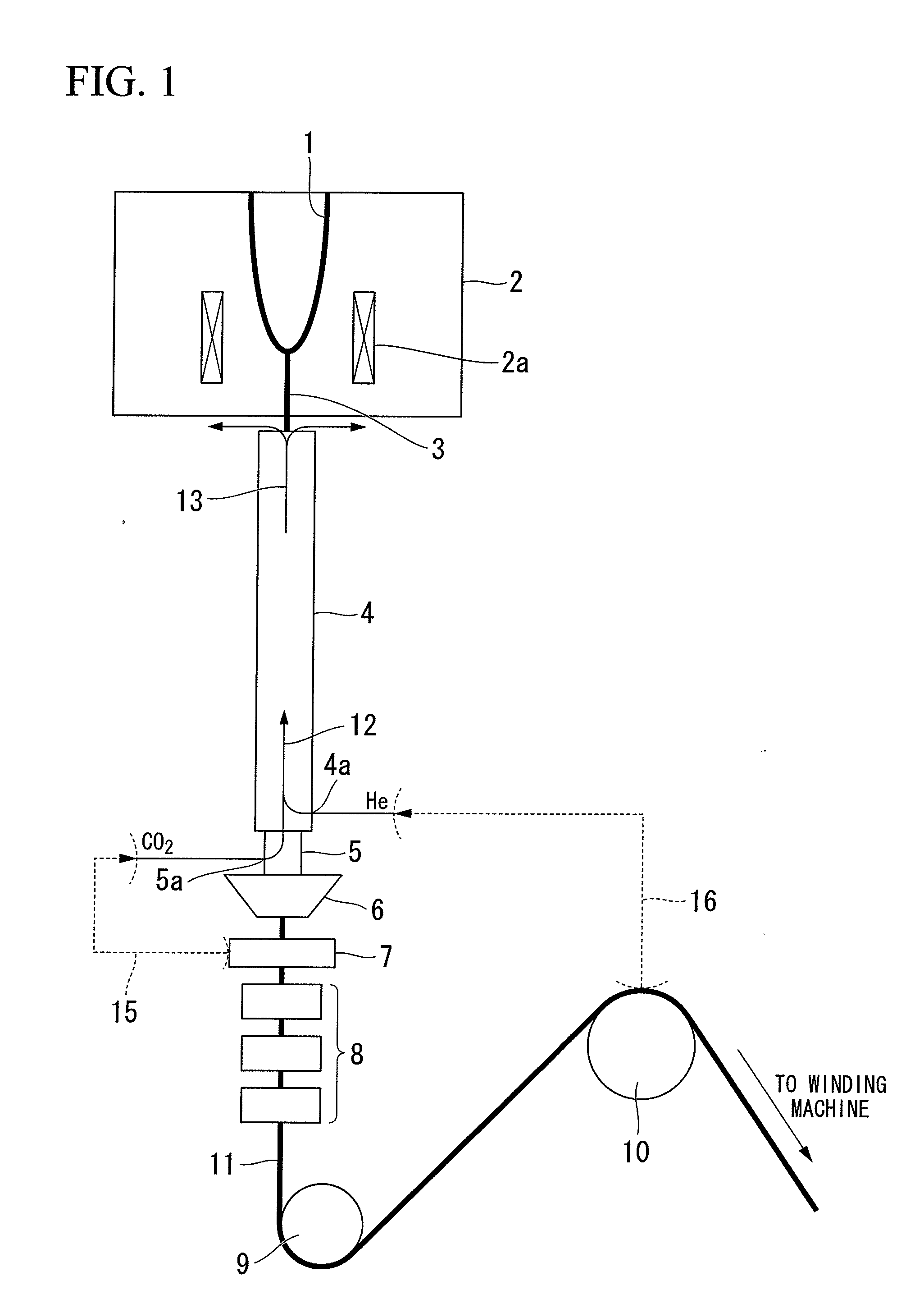
[0135]In the configuration of the apparatus shown in FIG. 1, an optical fiber is drawn at a center drawing speed of 1500 in / min, and the optical fiber is manufactured.

[0136]The cooling device which are not connected to the heating furnace and the coating device are connected together by the connecting member. Piping is arranged such that helium gas is made to flow into the lower portion of the cooling device, and piping is arranged such that carbon dioxide gas is made to flow into the upper portion of a coating device. The length of the connecting member is 300 mm. As the cooling device, five cylinders made of brass in which the internal diameter φ is 10 mm, the shape of the inner wall is flat, and the length is 1 m are connected together and used, and the cooling length of the cooling device is 5 m. Additionally, the temperature of the cooling water which circulates through the inside of a circulating water cylinder is 20° C.

[0137]Feedback control of the flow rate of the carbon dio...

example 2

[0139]An optical fiber is manufactured similarly to Example 1 except that the internal diameter φ of the cooling device is 7 mm, the total flow rate of the gas within the cooling device is 2 SLM, the flow rate of the helium gas is 1.5 SLM, and the flow rate of the carbon dioxide gas is 0.5 SLM.

[0140]The temperature of the bare optical fiber and the temperature of the mixed gas are measured. The temperature of the bare optical fiber introduced into the cooling device is 1100° C., the temperature of the cooling gas (the mixed gas of the helium gas and the carbon dioxide gas) introduced into the cooling device is 25° C., and the temperature of the mixed gas discharged from the upper end of the cooling device is 99° C. In this state, drawing of an optical fiber of a total of 10,000 km is implemented. As a result, the responsiveness of the cooling capacity of the cooling device and the resistance against a disturbance are excellent, and the coating diameter of the manufactured optical fi...

example 3

[0141]An optical fiber is manufactured similarly to Example 1 except that the internal diameter φ of the cooling device is 15 mm, the shape of the inner wall of the cooling device is formed into a concavo-convex shape (refer to FIG. 4), the total flow rate of the gas within the cooling device is 10 SLM, the flow rate of the helium gas is 8 SLM, and the flow rate of the carbon dioxide gas is 2 SLM. In this example, the inner wall 14a of the cooling device is formed with the convex portions 14f, and thereby a concavo-convex shape is formed within the cooling device to increase the surface area within the cooling device. Therefore, the heat exchange between the inner wall of the cooling device and the gas within the cooling device becomes better.

[0142]The temperature of the bare optical fiber and the temperature of the mixed gas are measured. The temperature of the bare optical fiber introduced into the cooling device is 1100° C., the temperature of the cooling gas (the mixed gas of th...


PUM

PropertyMeasurementUnit
diameteraaaaaaaaaa
temperatureaaaaaaaaaa
diameteraaaaaaaaaa

Abstract

A method for manufacturing an optical fiber in which a flow of a cooling gas within a cooling device is made to be an upward flow and the cooling gas is discharged to outside from an upper end of the cooling device by connecting the cooling device and a coating device in an airtight manner, and closing a flow of the cooling gas which flows toward a coating device within the cooling device using a meniscus of resin within the coating device. A temperature of the cooling gas is increased toward an upper portion of the cooling device from a lower portion of the cooling device by adjusting the flow rate of the cooling gas.

Description

CROSS-REFERENCE TO RELATED APPLICATION[0001]This is a Continuation Application of International Application No. PCT / JP2010 / 002761, filed Apr. 16, 2010, which claims priority to Japanese Patent Application No. 2009-100044, filed Apr. 16, 2009. The contents of the aforementioned application are incorporated herein by reference.BACKGROUND OF THE INVENTION[0002]1. Field of the Invention[0003]The present invention relates to a method for drawing an optical fiber preform to manufacture an optical fiber, in a manufacturing process of an optical fiber.[0004]2. Description of the Related Art[0005]FIG. 15 is a schematic configuration view showing a general apparatus for manufacturing an optical fiber. A method for manufacturing an optical fiber using this manufacturing apparatus includes the following steps.[0006](1) Inserting an optical fiber preform 101 which is formed from a glass rod which becomes a source of an optical fiber into a heating furnace 102. Then, a tip of the optical fiber pr...

Claims


Application Information

Patent Timeline
Patent Type & Authority Applications(United States)
IPC IPC(8): G02B6/00C03C25/10C03B37/026
CPCC03B37/02718C03C25/12C03B2205/55Y02P40/57C03B37/12G02B6/00G02B6/44
Inventor OKADA, KENJI
Owner THE FUJIKURA CABLE WORKS LTD
Why Eureka
Try Eureka