Sol solution and method for film formation

a technology of sol solution and film, applied in the manufacture of electrode systems, other chemical processes, electric discharge tubes/lamps, etc., can solve the problems of high equipment and productivity cost, high cost of equipment and productivity, and the possibility of agglomeration of fine particles of magnesium oxide, etc., to accelerate the reaction and enhance the stability of sol solution

Inactive Publication Date: 2000-11-21
DAI NIPPON PRINTING CO LTD
View PDF7 Cites 24 Cited by
  • Summary
  • Abstract
  • Description
  • Claims
  • Application Information

AI Technical Summary

Benefits of technology

A dispersion stabilizer may be incorporated into the sol solution in order to enhance the stability of the sol solution. Examples of preferred dispersion stabilizers include water-soluble polymers, for example, celluloses, such as hydroxypropyl methylcellulose and hydroxypropylmethyl cellulose, acrylic polymers, such as polyacrylic acid and polyacrylamide, and vinyl polymers, such as polyvinyl alcohol and a partially saponified product thereof. They may be used alone or a mixture of two or more, and the content of the dispersion stabilizer in the sol solution is usually in the range of from 0.01 to 10% by weight.
The sol solution containing magnesium acetate particles dispersed in a colloidal form can be prepared by adding anhydrous or partially hydrated magnesium acetate to medium composed mainly of water with a water-soluble solvent and a dispersion stabilizer being optionally dissolved therein and stirring the mixture. A reaction for forming the colloid smoothly proceeds at room temperature. However, heating to, for example, 30 to 80.degree. C. can accelerate the reaction.

Problems solved by technology

Among the above methods, those using a vacuum process, such as EB deposition, sputtering, and CVD, are disadvantageous in that it is difficult to accommodate a large panel substrate, like a plasma display, in a vacuum chamber, posing problems of cost of equipment and productivity when an increased screen size is assumed.
At the present time, however, no satisfactory performance could have been attained yet.
However, fine particles of magnesium oxide are likely to agglomerate and become very difficult to be homogeneously dispersed in the binder.
For this reason, in the conventional commercially available printing paste, the diameter of incorporated magnesium oxide particles per se is large and the viscosity of the paste per se is high, making it difficult to reduce the thickness of the protective layer.
Consequently, no highly even protective film can be formed.
Further, the conventional printing paste is disadvantageous in that the conventional heat treatment process (600.degree. C. or below) cannot offer satisfactory film strength, adhesion and other properties and heat treatment causes cracking of the film.
The coatability of the paste is also unsatisfactory.
Furthermore, the magnesium oxide particles incorporated are large, and the viscosity of the paste per se is high, making it difficult to reduce the layer thickness.
This in turn poses a problem that a demand for minimized firing voltage and drive voltage cannot be met.
This method, however, is disadvantageous in that the adhesion of the magnesium hydroxide sol to the substrate is so poor that a part of the resultant magnesium oxide layer is easily separated from the substrate and the film thickness is uneven.
Therefore, the above method is substantially ineffective in improving the firing voltage and the drive voltage (power consumption).
Further, heat treatment of the magnesium hydroxide sol at a conventional temperature (600.degree. C. or below) does not accelerate the crystallization of the resultant magnesium oxide.
Therefore, the film thus obtained has a low crystallinity and, hence, unsatisfactory film strength, causing a problem that properties as a protective film cannot be satisfactorily exhibited.
Magnesium alkoxides and the like involve a problem of cost, because they are very expensive, and, in addition, a problem associated with handling because the reactivity of the magnesium alkoxides is so high that the control of the reaction is difficult and the life of the resultant magnesium hydroxide is short.

Method used


Image

  • Sol solution and method for film formation
  • Sol solution and method for film formation
  • Sol solution and method for film formation

Examples


example c1

Preparation of Sol Solution

(1) Dehydration of magnesium acetate tetrahydrate

A commercially available magnesium acetate tetrahydrate was dried at 120.degree. C. for 5 hr in a vacuum dryer to prepare anhydrous magnesium acetate from which the hydrate had been completely removed.

(2) Preparation of sol solution containing dispersed colloidal particles of magnesium acetate

3 parts of the anhydrous magnesium acetate particles was added to an aqueous solution of 0.1 part of hydroxypropylmethyl cellulose in 97 parts of water, and the mixture was stirred at room temperature for 3 hr.

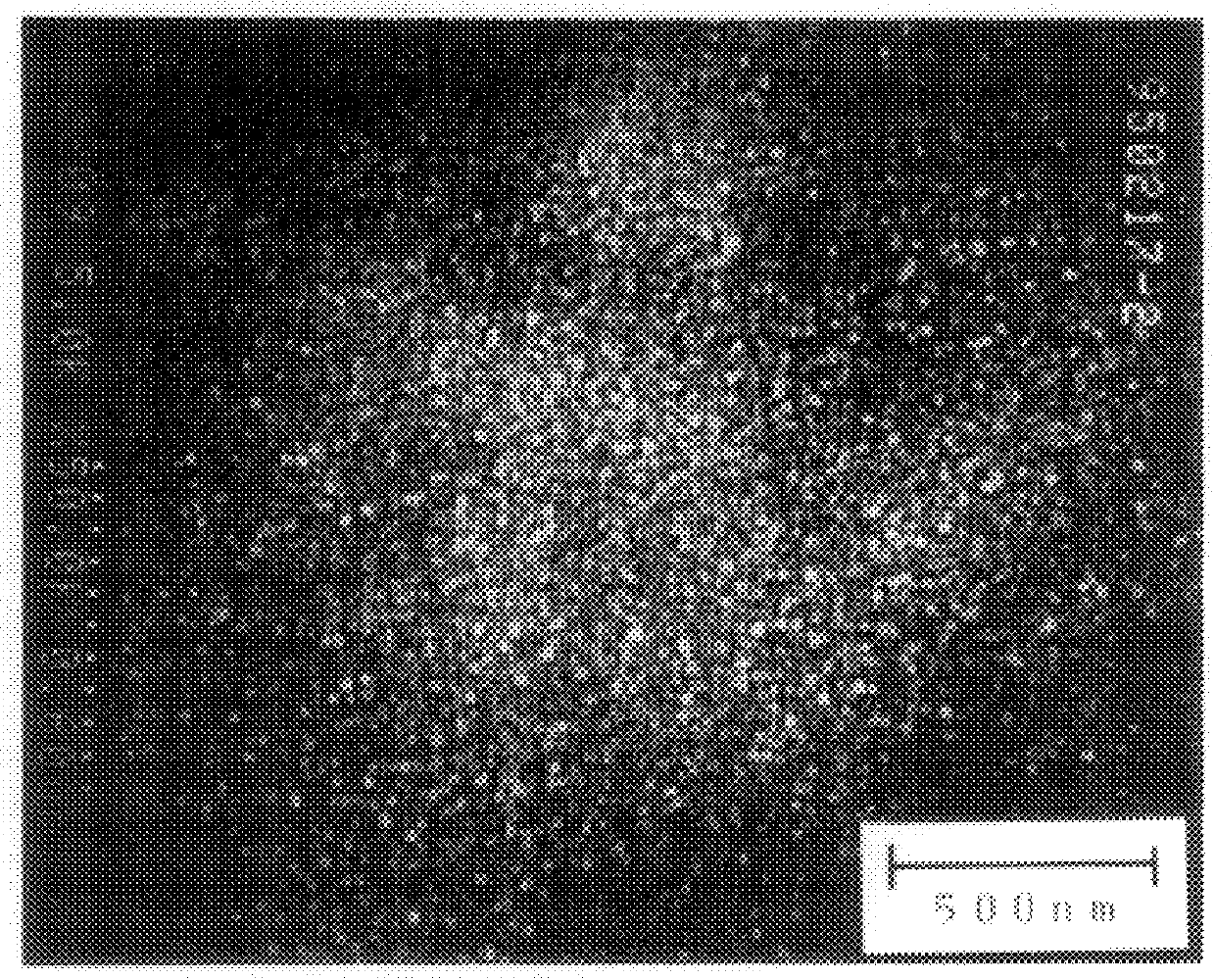
In the resultant sol solution with colloidal particles of magnesium acetate dispersed in water, the diameter of the colloidal particles was 120 nm. The sol solution was allowed to stand at room temperature for one month. As a result, it was stable, and settling of magnesium acetate was not observed.

example c2

Formation of Protective Layer on Alternating Current Type PDP

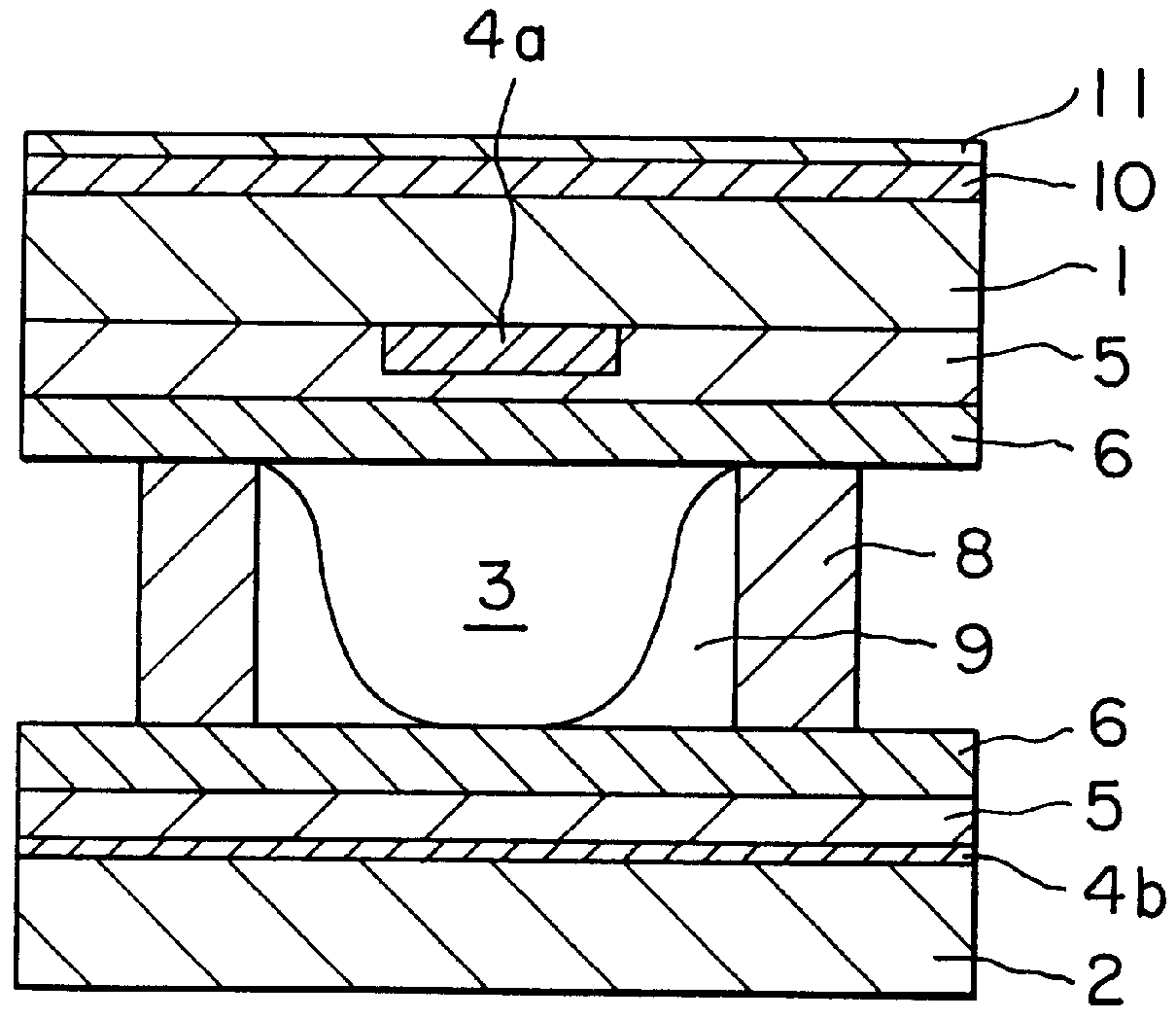
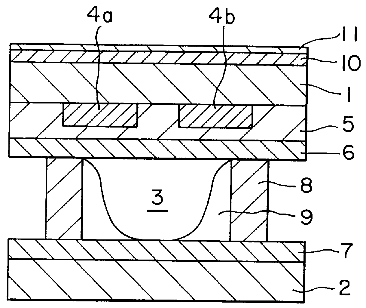
The formation of a protective layer, for an alternating current type PDP, using the sol solution prepared in Example C1, applied to a display (a panel), of a color television will be described. Embodiments of the construction of such a panel are shown in FIGS. 1 and 2.

As shown in FIG. 1 (plane discharge system), the display comprises a front substrate 1 and a back substrate 2 disposed opposite to each other with a gas discharge space 3 sandwiched between these two substrates. The substrates 1 and 2 are formed of a glass plate having a predetermined thickness. A pair of electrodes 4 of an electrode X 4a and an electrode Y 4b are provided on the substrate 1 in its side facing the substrate 2, and a dielectric layer 5 is formed on the substrate 1 so as to cover the electrodes. The dielectric layer 5 is covered with a protective layer 6. In general, the thickness of the protective layer 6 should be not more than 2 .mu.m. An ad...


PUM

PropertyMeasurementUnit
diameteraaaaaaaaaa
temperatureaaaaaaaaaa
sizeaaaaaaaaaa

Abstract

A method for forming a protective layer for a dielectric material in an alternating current type plasma display is provided. In this connection, a coating sol solution is provided which can form a protective layer on a large area substrate without the need to introduce any expensive equipment, the protective layer thus formed being excellent in properties such as strength, adhesion, transparency, and protective properties and capable of being formed by a sol-gel process without use of the conventional vacuum process. The sol solution comprises a dispersion of a precursor to magnesium oxide in a specific form. A method for film formation, using this solution is also provided.

Description

The present invention relates to a sol solution and a method for film formation, and more particularly to a sol solution useful for the formation of a protective layer for a dielectric layer in an alternating current type plasma display and a method for film formation using the sol solution.For optical components, electronic and electrical components, magnetic material components and the like, layers having various functions are formed on the substrate, and, if necessary, a protective film is provided on the surface of these layers for protection purposes. High film strength and large adhesion to the above functional layers are general properties required of such protective films.In recent years, research and development of flat panel displays as an alternative to CRT have been energetically conducted. Among them, the so-called "plasma display" which utilizes luminous phenomenon accompanying discharge in a display is classified, according to the structure of the electrode (mainly IT...

Claims


Application Information

Patent Timeline
Patent Type & Authority Patents(United States)
IPC IPC(8): B01J13/00C03C17/25C07F3/00H01J9/02
CPCB01J13/0008C03C17/25C07F3/003H01J9/02C03C2217/228H01J2217/49207C03C2218/113
Inventor MITAMURA, SATOSHIYOSHIHARA, TOSHIOTAKAHASHI, NOBUKO
Owner DAI NIPPON PRINTING CO LTD
Why Eureka
Try Eureka