
Valve treatment devices, systems, and methods

Active Publication Date: 2015-03-05
MITRAGEN
View PDF11 Cites 3 Cited by
  • Summary
  • Abstract
  • Description
  • Claims
  • Application Information

AI Technical Summary

Benefits of technology

The present invention is a medical device system for treating a valve in a heart to minimize valve regurgitation. The system includes an RF energy source, a handle, a treatment catheter, and first and second sleeves. The first and second sleeves are moveable between a constricted position and an expanded position and are independently moveable relative to the treatment catheter. The first and second electrodes have a helical configuration with a sharp distal tip that can twist into tissue of the valve. The treatment catheter is steerable along its distal portion to multiple orientations. The system also includes one or more temperature sensors and a third sleeve for sensing tissue temperature. The technical effects of the invention include improved treatment of valve regurgitation with reduced valve leakage and improved safety during the procedure.

Problems solved by technology

In contrast, the geometry is enlarged in an unhealthy mitral valve, which may prevent the leaflets from fully closing, resulting in mitral regurgitation.
Such procedures are expensive, extremely invasive requiring considerable recovery time and, most significantly, pose mortality risks.
Further, such open heart procedures are particularly stressful on patients whom already have a cardiac condition.
Moreover, the effectiveness of such procedures is difficult to assess during the procedure and may not be known until a much later time.
Therefore the ability to make adjustments or modifications to the prostheses in order to obtain optimum effectiveness is extremely limited.
Although these methods have had some success and are non-invasive, the procedures are long and cumbersome, often taking several hours to complete.
Further, due to leaving an implanted medical device in the heart, should the patient need additional subsequent procedures if, for example, regurgitation at the mitral valve again becomes an issue or the original regurgitation at the mitral valve is not corrected, another implanted device to correct the problem may be impossible at which time the patient's options may be limited to open heart surgery.

Method used


Image

  • Valve treatment devices, systems, and methods
  • Valve treatment devices, systems, and methods
  • Valve treatment devices, systems, and methods

Examples


Embodiment Construction

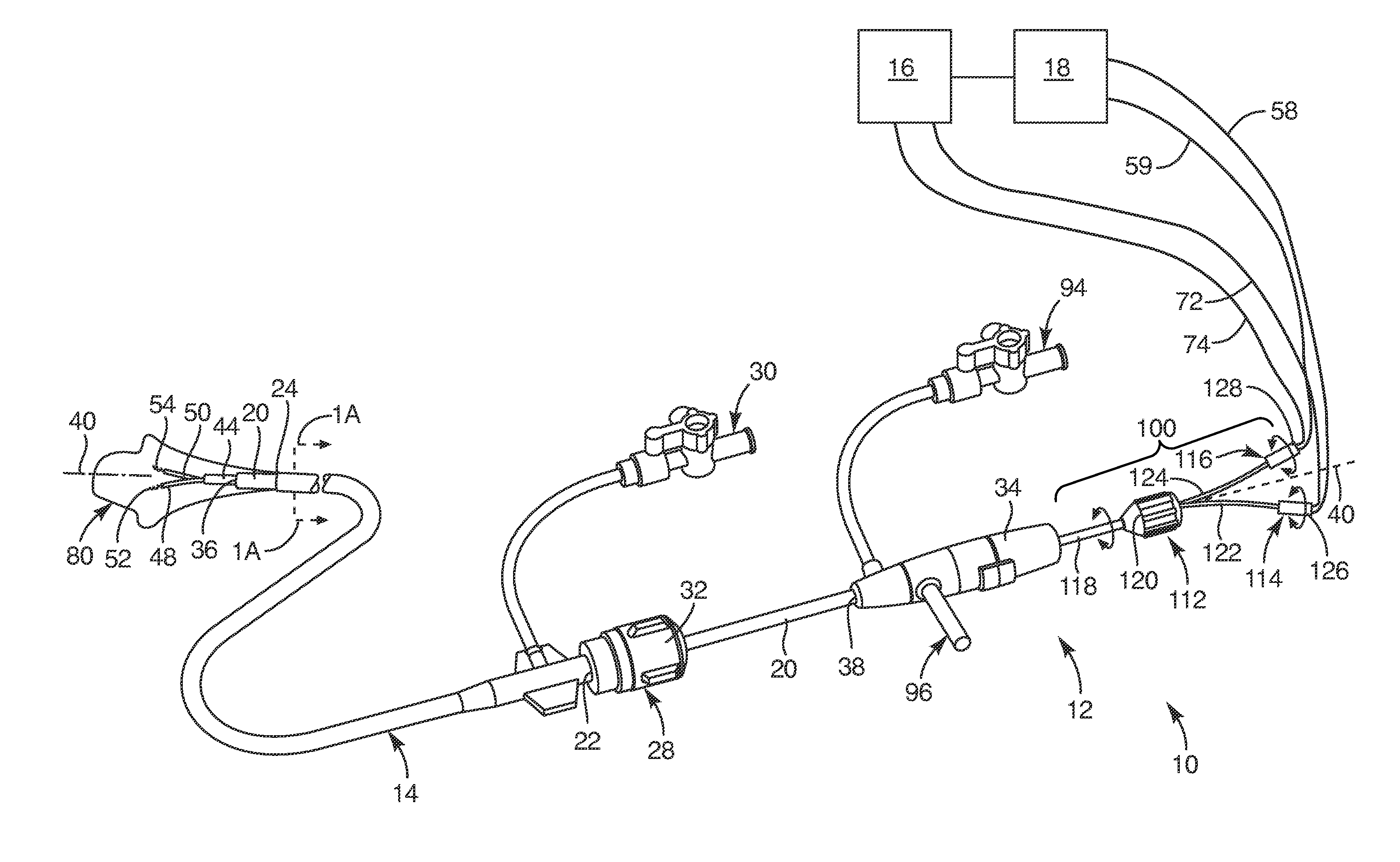
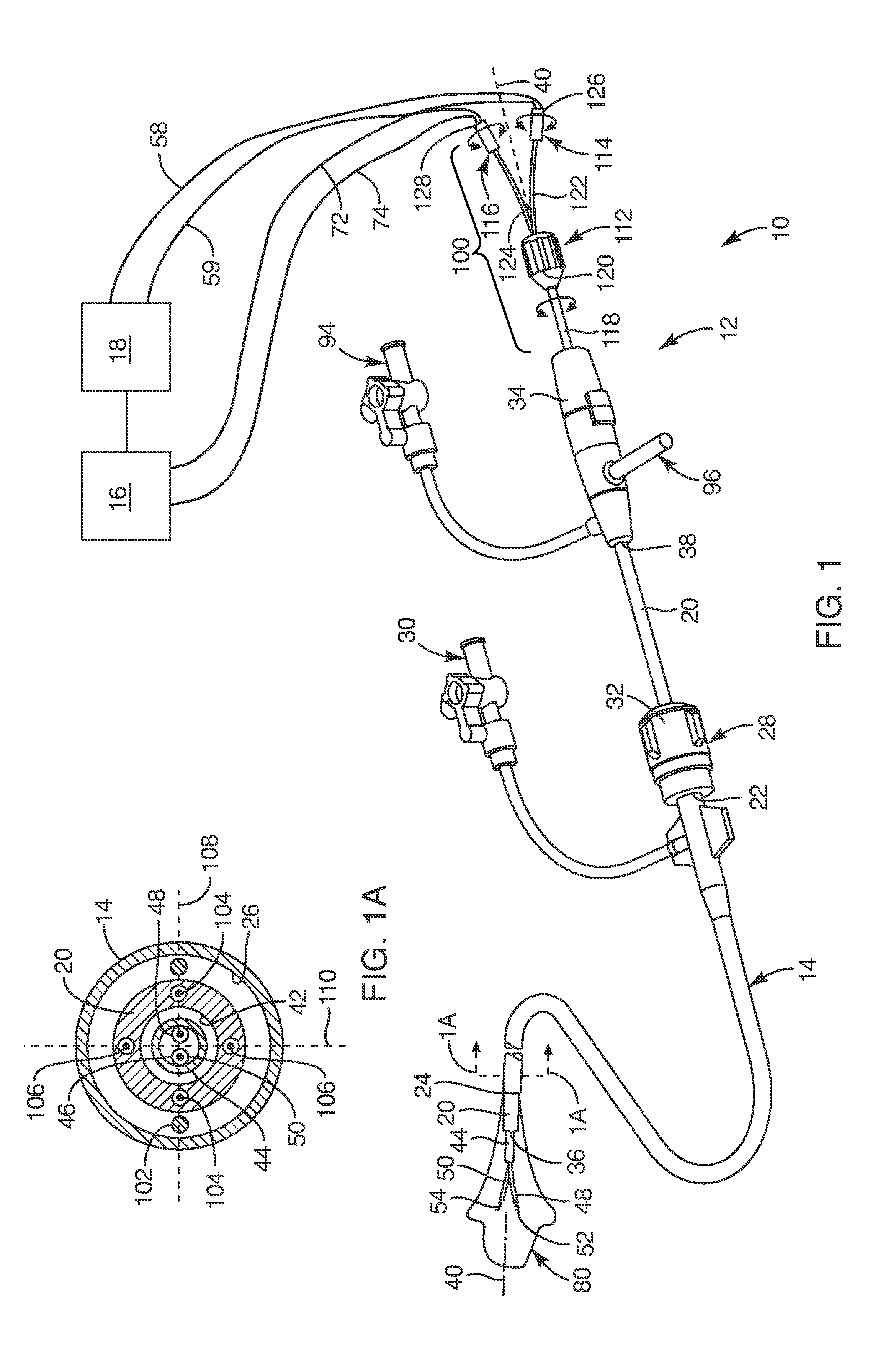
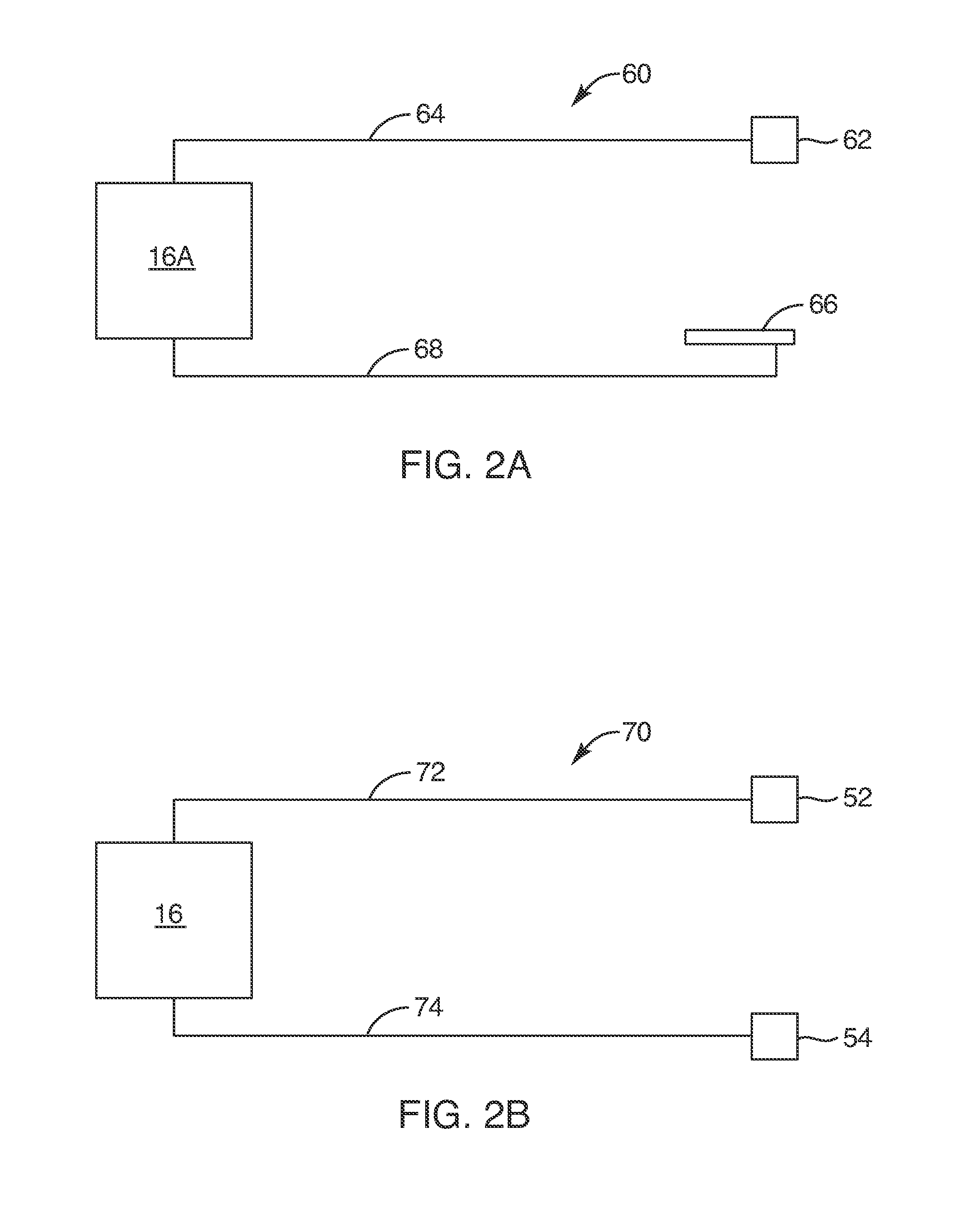
[0057]Referring first to FIG. 1, a medical device system 10 for treating valve regurgitation is provided. The medical device system 10 may include a treatment catheter system 12, a sheath 14, and a radio frequency (“RF”) energy source 16. The RF energy source 16 may also be coupled to a controller 18 such that the controller 18 may be housed with the RF energy source 16. With such a medical device system 10, a distal portion of the sheath 14 may be advanced and positioned in the left atrium of the heart so that the treatment catheter system 12 may then be advanced through the sheath 14 to, for example, a valve in the heart, such as a mitral valve 170 (see FIG. 4). The treatment catheter system 12 may include one or more electrodes to be positioned to contact tissue of the valve, for example, the tissue of the posterior annulus of the valve. The one or more electrodes may be employed to heat the tissue of the valve to a predetermined temperature range with the RF energy source 16 at ...


PUM


Abstract

Medical device systems, methods and devices are provided for treating a valve in a heart to minimize valve regurgitation, the medical device system includes an RF energy source, a handle, a treatment catheter, and first and second sleeves. The handle is operatively coupled to the RF energy source and coupled to the treatment catheter. The first and second sleeves each extend through a lumen of the treatment catheter and are moveable between a constricted position and an expanded position. The first sleeve includes a first electrode and the second sleeve includes a second electrode. Further, the first sleeve and the second sleeve are biased away from each other such that, upon being moved to the expanded position, the first and second sleeves splay outward to exhibit a v-configuration.

Description

CROSS-REFERENCE TO RELATED APPLICATIONS[0001]The present application claims the benefit of U.S. Provisional Application No. 61 / 874,313, filed Sep. 5, 2013, and U.S. Provisional Application No. 61 / 895,478, filed on Oct. 25, 2013, the disclosures of which are hereby incorporated by reference in their entirety. This application relates to U.S. patent application Ser. No. ______, filed Sep. 2, 2014, titled VALVE TREATMENT DEVICES, SYSTEMS, AND METHODS (Attorney Docket No. 135P2.1US), the disclosure of which is hereby incorporated by reference in its entirety.TECHNICAL FIELD[0002]The present invention relates generally to devices, systems, and methods for limiting valve regurgitation. More particularly, the present invention relates to medical devices, systems, and methods for percutaneously treating valves in, for example, the heart to limit valve regurgitation.BACKGROUND[0003]The human heart generally includes four valves: the mitral valve, the tricuspid valve, the aortic valve, and th...

Claims


Application Information

Patent Timeline
IPC IPC(8): A61B18/14A61B18/12
CPCA61B18/1492A61B18/1206A61B2018/00369A61B2018/00791A61B2018/1425A61B2018/126A61B2018/1435A61B2018/143A61B2018/1253A61B90/39A61B2018/00654A61B2018/00714A61B2018/00797A61B2018/00821A61B2018/1407A61B2018/1475A61B2090/3966
Inventor MILES, SCOTT D.DAHL, VERNON D.
Owner MITRAGEN
Learn More