

Gaseous Flow Sensor and Related Method Thereof
a gaseous flow and sensor technology, applied in the field of sensors, can solve the problems of long-term sensor drift and heat loss-induced long-term operation sensor drift, and achieve the effect of reducing sensor dri
Active Publication Date: 2015-03-12
UNIV OF VIRGINIA ALUMNI PATENTS FOUND
View PDF6 Cites 16 Cited by
- Summary
- Abstract
- Description
- Claims
- Application Information
AI Technical Summary
Benefits of technology
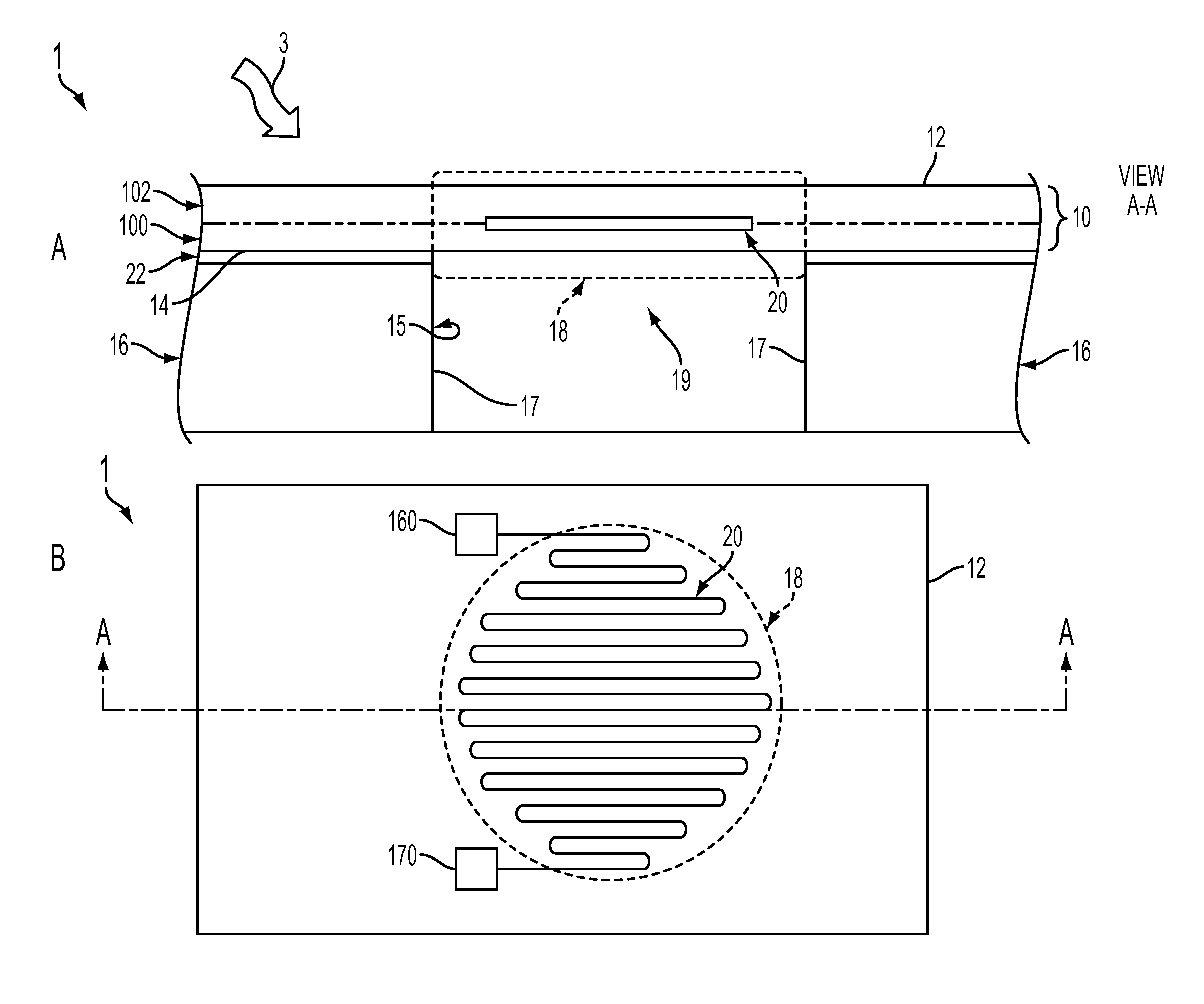
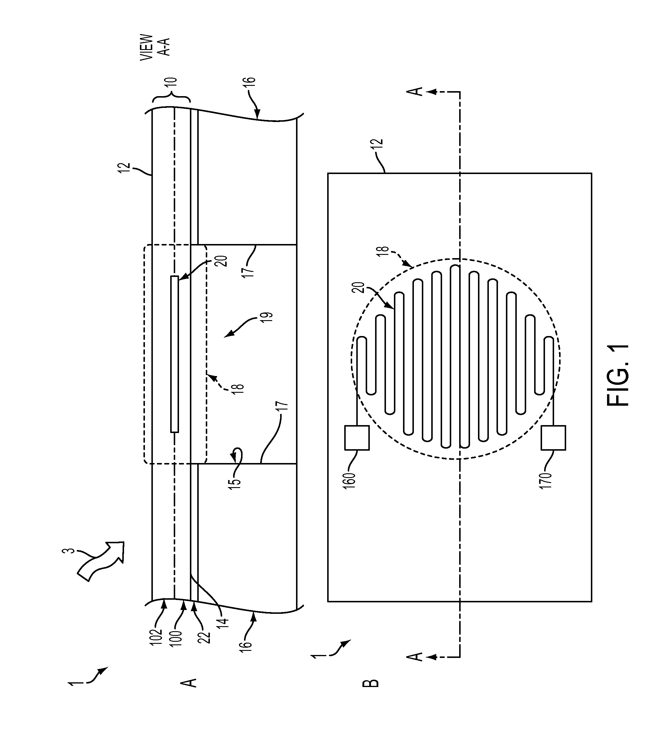
The present invention is a gas flow sensing device that includes a conductive layer encapsulated in a dielectric film, forming a diaphragm. The conductive layer acts as both a heating element and a sensing element, providing uniform heat distribution across the diaphragm. The design of the device allows for sensing flow from any direction and reduces sensor drift during prolonged use. Additionally, the device can sense flow from any in-plane gas flow in any direction.
Problems solved by technology
Heat loss from the associated heating element to the substrate during operation causes long-term sensor drift.
However, to date, the problem of long-term operation sensor drift caused by heat loss has not been solved, much less for commercially available flow sensors.
Method used
View moreImage
Smart ImageViewing Examples

Examples
example 1
[0077]A low power electronic sensing device for use measuring gaseous flow. The device may comprise: a dielectric layer with a first surface in communication with a flow to be measured; a substrate in communication with a second surface of the dielectric layer; a cavity in the substrate, wherein a portion of the dielectric layer being substantially in communication with the cavity to form a diaphragm; and a conductive layer disposed on or inside the diaphragm.
example 2
[0078]The device of example 1, wherein the conductive layer is metallic.
example 3
[0079]The device of example 1 (as well as subject matter of example 2), wherein the substrate is substantially rigid.
Login to View More PUM
| Property | Measurement | Unit |
|---|---|---|
| length | aaaaa | aaaaa |
| length | aaaaa | aaaaa |
| thickness | aaaaa | aaaaa |
Abstract
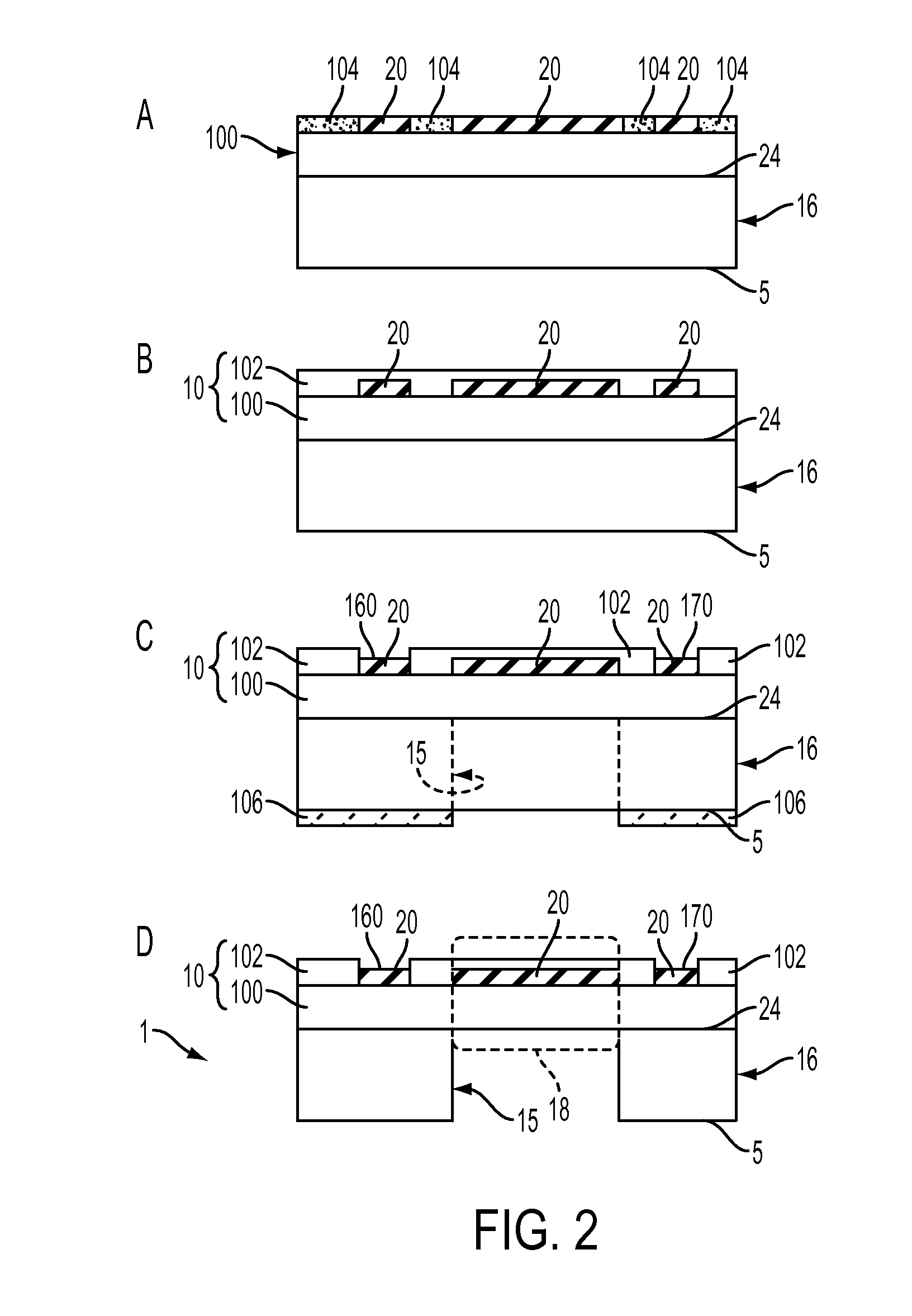
A gas flow sensing device, and related method of manufacturing, comprising a conductive layer encapsulated in dielectric film, suspended over a cavity to form a diaphragm. The conductive layer functions as both a heating a sensing element and is patterned to provide uniform heat distribution across the diaphragm. The device is designed to sense flow from any direction relative to the device and the design of the dielectric film and diaphragm reduces sensor drift during prolonged operation.
Description
CROSS REFERENCE TO RELATED APPLICATIONS[0001]The present application claims priority under 35 U.S.C. §119(e) from U.S. Provisional Application Ser. No. 61 / 622,979, filed Apr. 11, 2012, entitled “Flow Sensor and Methods of Use and Fabrication of the Same;” the disclosure of which is hereby incorporated by reference herein in its entirety.STATEMENT OF GOVERNMENT INTEREST[0002]The present invention was developed with United States Government Support under Office of Naval Research Grant No. N00014-08-1-0642. The government has certain rights in the invention.FIELD OF THE INVENTION[0003]The present invention relates generally to the field of sensors. More specifically, the invention relates to the subfield of gaseous flow sensors.BACKGROUND OF THE INVENTION[0004]There have been developments in Micro-Electro-Mechanical Systems (MEMS) and microfabrication technology, which facilitates the measurement of flow rate with a miniature chip.[0005]For one type of thermal flow sensor, it measures ...
Claims
Login to View More Application Information
Patent Timeline
 Patent Type & AuthorityApplications(United States)
IPC IPC(8): G01F1/684H05K3/46H05K3/00
CPCG01F1/684H05K3/46H05K3/0011G01F1/6845G01F1/692G01F1/696G01F15/006Y10T29/49155
InventorZHU, JIANZHONGBART-SMITH, HILARYCHEN, ZHENG
OwnerUNIV OF VIRGINIA ALUMNI PATENTS FOUND