
Geonet for a geocomposite

a geocomposite and geotextile technology, applied in the field of geocomposites, can solve the problems of reducing the flow rate through the geotextile, requiring large amounts of valuable land, and reducing the flow rate as well, so as to facilitate the draining of liquid

Inactive Publication Date: 2015-03-12
GSE ENVIRONMENTAL
View PDF14 Cites 4 Cited by
  • Summary
  • Abstract
  • Description
  • Claims
  • Application Information

AI Technical Summary

Benefits of technology

The present invention provides a geonet for use in geotechnical construction sites that has a length greater than its width. The geonet includes a first layer of strands and a second layer of strands that are at an angle relative to the first layer. The strands are secured to one another at crossover locations. The geonet can be stored in a roll with X number of layers, where each strand of the first layer is rolled X times. The geonet can be made using a mold with openings for the strands. The technical effect of the invention is to provide a geonet that can be easily transported and installed in construction sites, and that can be used to reinforce the ground and support structures.

Problems solved by technology

Waste collection sites are, of course, one well known type of geotechnical construction site, and are unavoidably required in today's societal structures, Such sites can require large amounts of valuable land, particularly in urban areas where large amounts of waste are generated and, at the same time, land is most in demand.
Also, while desirable uses can be made of such lands (for example, golf courses have been built on such sites), such desirable uses typically have to wait until the land is no longer being used for collect further waste and the often high pile of waste has stabilized.
However, given the large loads which such geotextiles are subjected to as more and more layers of land mass are piled on top of the layers, compression and / or collapse of the geotextile and result, thereby reducing the flow rate through the geotextile.
Further, while additional components, etc. may be added to strengthen the geotextile against collapse, those additional components may themselves block and thereby reduce the flow rate as well.

Method used


Image

  • Geonet for a geocomposite
  • Geonet for a geocomposite
  • Geonet for a geocomposite

Examples


Embodiment Construction

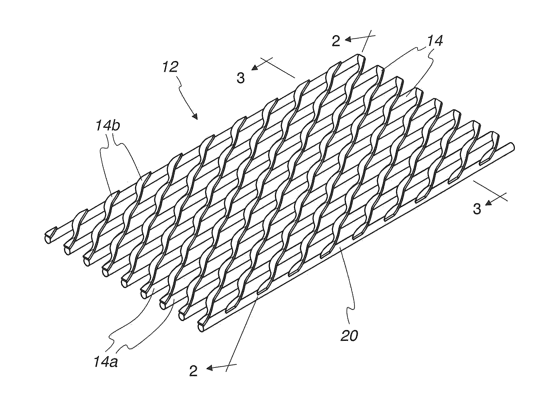
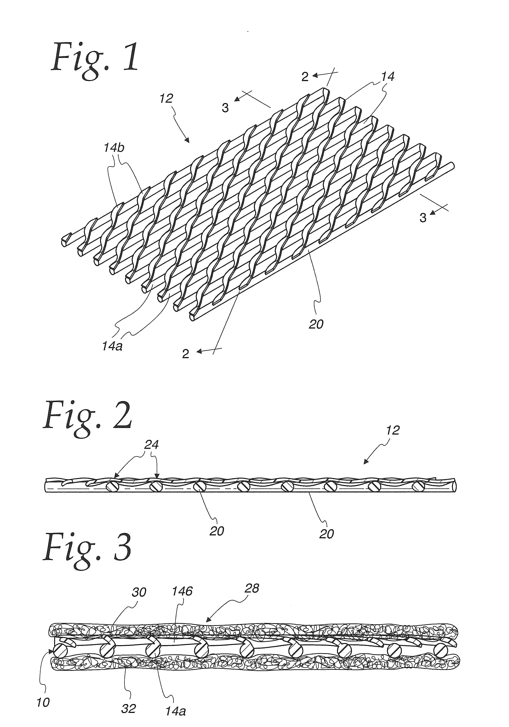
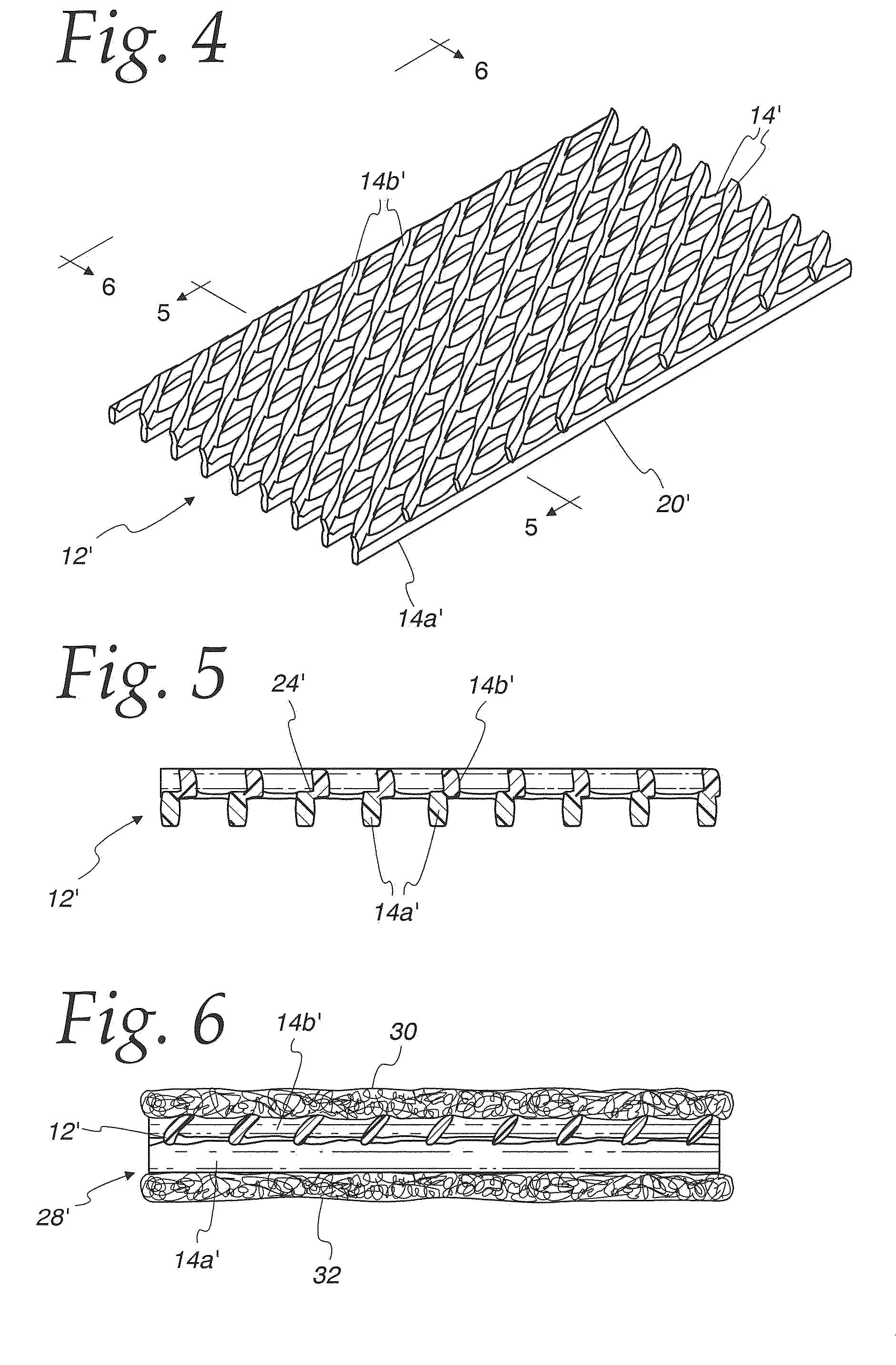
[0040]One embodiment of a geonet 12 according to the present invention is shown in FIGS. 1-2. The geonet 12 consists of substantially incompressible longitudinal strands 14 (e.g., formed of polyethylene [PE], including but not limited to high density polyethylene [HDPE]), including a lower set of a plurality of substantially parallel strands 14a and an upper set of a plurality of substantially parallel strands 14b. Advantageously, one set of strands 14a extends parallel to the longitudinal direction of the geonet 12, and the other set of strands 14b is at an angle of 45° to 70° relative to the longitudinal strands 14a so that a crisscrossed grid 20 is formed (see FIG. 1).

[0041]It should be understood that as used herein, “substantially incompressible” is meant to refer to materials such as HDPE which, though susceptible to bending, breaking, fracture and / or creep, does not appreciably compress in the vertical direction when vertical forces are applied,

[0042]At their overlapping inte...


PUM

PropertyMeasurementUnit
angleaaaaaaaaaa
angleaaaaaaaaaa
thickaaaaaaaaaa

Abstract

A geonet having a length substantially greater than its width and including no more than first and second layers of strands. A first plurality of substantially parallel strands extends in the lengthwise direction and defines the first layer of strands, and a second plurality of substantially parallel strands is disposed on top of, and at an angle relative to, the first plurality of strands and defines the second layer of strands. The first and second plurality of strands are substantially incompressible and secured to one another at crossover locations. Geocomposites include geotextile bonded to at least one side of the geonet. The geonets / geocomposites are laid in geotechnical construction sites in the direction of expected drainage flow.

Description

CROSS-REFERENCE TO RELATED APPLICATIONS[0001]This application is a divisional application of Ser. No. 11 / 891,168, filed Aug. 9, 2007, and entitled “Geonet for a Geocomposite”, the disclosure of which is hereby incorporated by reference.FEDERALLY SPONSORED RESEARCH OR DEVELOPMENT[0002]Not Applicable.MICROFICHE / COPYRIGHT REFERENCE[0003]Not Applicable.FIELD OF THE INVENTION[0004]The present invention is directed toward geocomposites for use in geotechnical construction sites, and particularly toward geonets usable with geotextiles in forming such geocomposites.BACKGROUND OF THE INVENTION[0005]Geotechnical engineering and the usage of geosynthetic materials are very common in today's civil engineering marketplace. One of the most common geosynthetic material available today are drainage products. Drainage products are generally comprised of a geonet or material or a geonet combined with a filtration fabric which may be one of many varieties. These products are used for a broad variety o...

Claims


Application Information

Patent Timeline
Patent Type & Authority Applications(United States)
IPC IPC(8): E02D31/00B29C47/00B29C47/24E02B11/00B29C48/05B29C48/09B29C48/33
CPCE02D31/004E02D31/006E02B11/00B29C47/0066B29K2023/065B29C2793/0063B29C2793/009B29L2028/00B29C47/24B09B1/00B29K2023/06B32B5/12B32B5/26D04H3/04E02D17/202B32B5/022B32B2262/0253D04H3/045B29C48/13B29C48/301B29C48/345Y10T428/24273B29C48/0022B29C48/33B29C48/09B29C48/05
Inventor RAMSEY, BOYD J.
Owner GSE ENVIRONMENTAL
Learn More