Glenoid implant surgery using patient specific instrumentation

Active Publication Date: 2015-03-12
ZIMMER INC
View PDF10 Cites 66 Cited by
  • Summary
  • Abstract
  • Description
  • Claims
  • Application Information

AI Technical Summary

Benefits of technology

[0024]Still further in accordance with aspect of the present disclosure, forcing the implant into the resurfaced glenoid cavity

Problems solved by technology

One of the challenges when installing an implant in the glenoid relates to the positioning of implant

Method used


Image

  • Glenoid implant surgery using patient specific instrumentation
  • Glenoid implant surgery using patient specific instrumentation
  • Glenoid implant surgery using patient specific instrumentation

Examples


Embodiment Construction

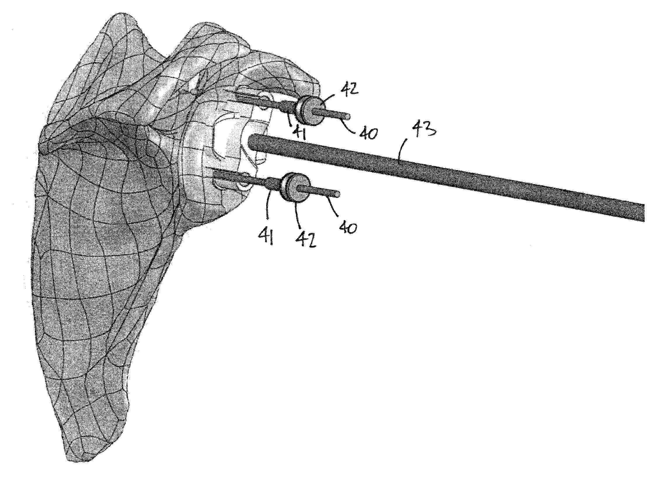
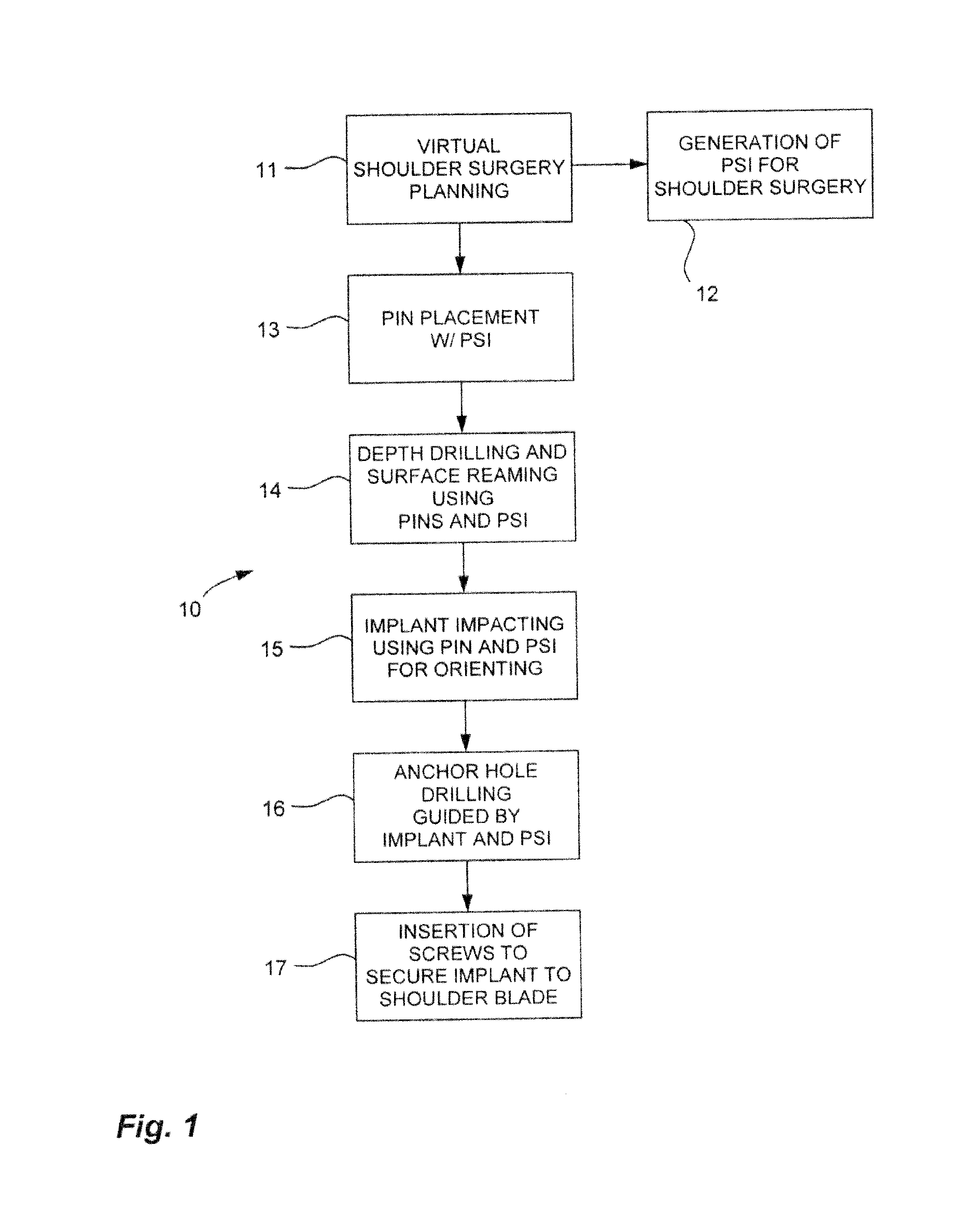
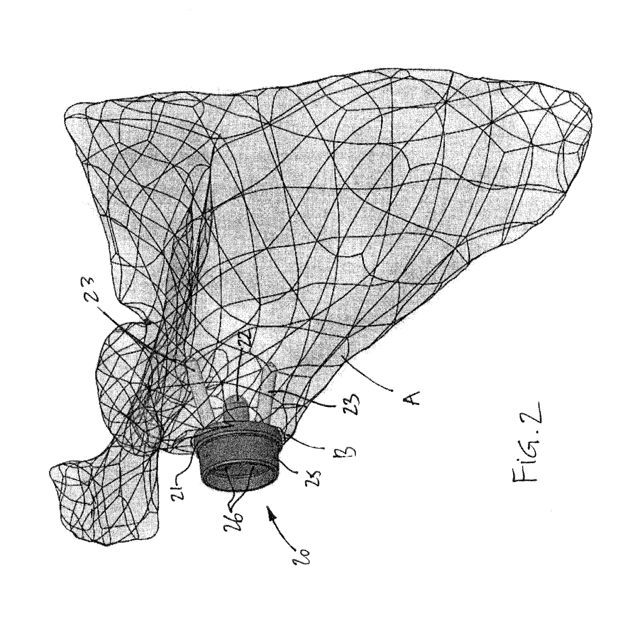
[0041]Referring to the drawings and more particularly to FIG. 1, there is illustrated at 10 a method for securing a glenoid implant on a scapula (i.e., scapula) In order to perform the method, patient specific instrumentation of various kinds are used, and will be referred to hereinafter as PSI, with reference to FIGS. 2-13. By way of example, FIG. 2 features the positioning of a glenoid hemispherical head implant base on the scapula, in reverse total shoulder surgery. However, the method 10 may alternatively be used to secure a cup implant in the glenoid as performed on anatomic total shoulder replacement.

[0042]According to step 11 of FIG. 1, virtual shoulder surgery planning is performed. In this planning step, various shoulder structures are displayed as three-dimensional models, along with a model implant and its components. These 3-D models are typically the result of the processing pre-operative imagery (e.g., CT scans, MRI, etc) and hence are a precise and accurate representa...


PUM


Abstract

A pin placement instrument for placing a pin in a bone comprises an anatomical interface with a hook-like portion being opened in a lateral direction of the instrument to receive a bone therein in a planned position. A drill guide is connected to the anatomical interface and defining at least one guide slot in a longitudinal direction of the instrument. The guide slot has a lateral opening over its full length in the drill guide to allow lateral withdrawal of the instrument in said lateral direction with the pin placed in the bone passing through the lateral opening. A bushing is removably placed in said guide slot via said longitudinal direction in a planned fit, the bushing defining a throughbore aligned with the guide slot and adapted to receive the pin extending in said longitudinal direction when the bushing is in the guide slot for pin placement.

Description

FIELD OF THE APPLICATION[0001]The present application relates to shoulder replacement, more specifically to glenoid implant shoulder surgery for instance in total shoulder replacement, and to patient specific instrumentation (PSI) used therefore.BACKGROUND OF THE ART[0002]The use of implants in shoulder surgery is well-known. In such shoulder surgery, implant components are installed on the glenoid portion of the scapula (i.e., shoulder blade) and / or on the humerus, to replicate the shoulder joint. When an implant is installed on the scapula, it is commonly installed in the glenoid cavity, also known as the glenoid or glenoid fossa. The glenoid is a cavity that receives the head of the humerus in an anatomical shoulder. When an implant is used with the glenoid, the base of the implant is located within the glenoid, and could be secured thereto by fasteners such as screws, or using cement and / or fixation peg or keel.[0003]One of the challenges when installing an implant in the glenoi...

Claims


Application Information

Patent Timeline
IPC IPC(8): A61B17/17A61B17/16A61F2/40
CPCA61B17/1739A61B2017/1778A61B17/1684A61F2/4081A61B34/10A61B17/8897A61B17/92A61F2/40A61F2/4612A61F2002/4011A61B2034/105A61B17/1778A61B17/90A61F2002/30736A61F2002/4085A61B2017/568
Inventor COUTURE, PIERREMERETTE, JEAN-SEBASTIENRICHARD, ALAINABIVEN, JEAN-GUILLAUMEGOURGON, THOMAS
Owner ZIMMER INC
Why Eureka
Try Eureka