Valve gear of engine

a valve gear and engine technology, applied in the direction of valve details, valve arrangements, valve drives, etc., can solve problems such as operational members suffering from malfunction

Active Publication Date: 2015-03-19
MAZDA MOTOR CORP
View PDF3 Cites 11 Cited by
  • Summary
  • Abstract
  • Description
  • Claims
  • Application Information

AI Technical Summary

Benefits of technology

[0006]The present invention has been devised to solve the above-described problem, and an object of the present invention is to provide a valve gear of...

Problems solved by technology

While it is necessary to drive the actuator so that the operational member can project or retreat at a desired timing...

Method used


Image

  • Valve gear of engine
  • Valve gear of engine
  • Valve gear of engine

Examples


Embodiment Construction

[0027]Hereinafter, a preferred embodiment of the present invention will be described referring to an example in which a valve gear according to the present invention is applied to a four-cylinder four-valve DOHC engine.

[0028](Schematic Structure of Valve Gear)

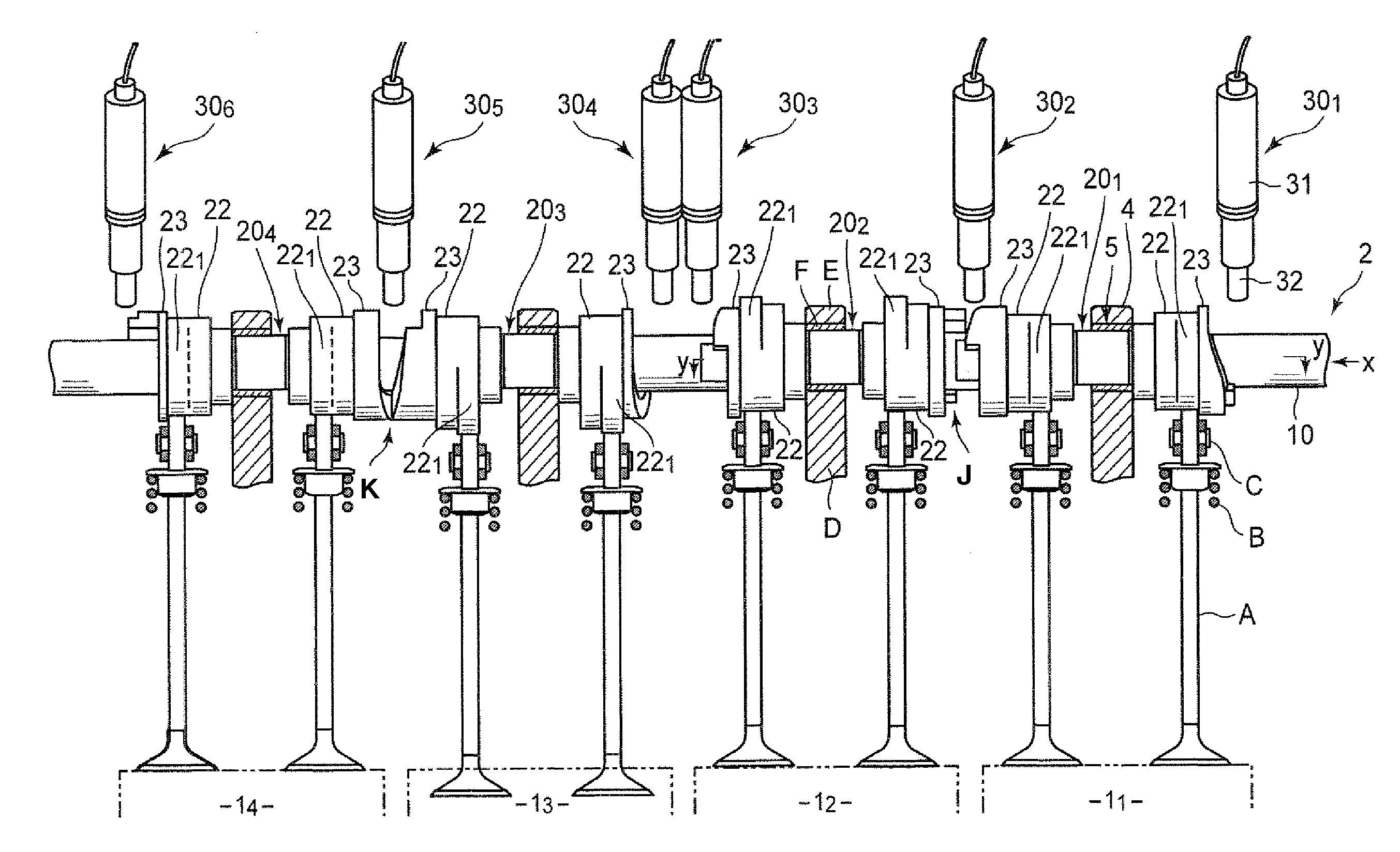
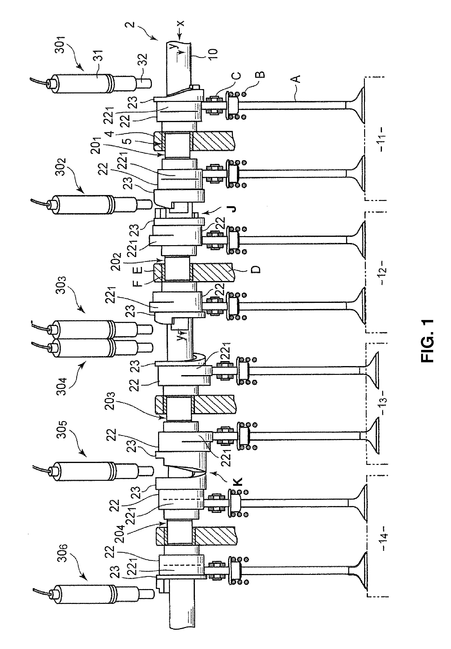
[0029]FIG. 1 shows a structure of an exhaust-side valve gear according to the present embodiment. This valve gear comprises, in total, eight exhaust valves A . . . A, two of which are provided at each of first—fourth cylinders 11-14, and return springs B . . . B operative to impel the exhaust valves A . . . A in a closing direction, which are provided at a cylinder head, not illustrated. Further, a camshaft 2 operative to open the exhaust valves A . . . A against an impelling force of the return springs B . . . B via rocker arms C . . . C is provided at an upper portion of the cylinder head.

[0030]The camshaft 2 is rotatably supported at journal portions F . . . F which are comprised of vertical wall portions D . . . D located a...


PUM


Abstract

A cam element portions is configured such that respective maximum lift portions (lift ending points) of both-side end-face cams thereof are provided at respective phases which are different from each other in a rotational direction and that a maximum value of a length, in an axial direction, between respective cam faces of the both-side end-face cams which are provided at the same phase is set to be a distance, in the axial direction, between a first operational member and a second operational member or smaller. Accordingly, in a valve gear of an engine in which cams operative to control opening/closing of a valve are switchable, it can be properly prevented that a camshaft locks and stop rotating because of an operational malfunction of an operational member or the like.

Description

BACKGROUND OF THE INVENTION[0001]The present invention relates to a valve gear of an engine for vehicles or the like, and particularly to a valve gear in which cams operative to control opening / closing of a valve are switchable.[0002]A valve gear of an engine, in which plural cams having different-shaped nose portions are provided for each valve, and the valve-opening amount, the valve opening-closing timing, and the like are configured to be changeable according to an engine's operation state through a selection of a specified cam for opening / closing the valve from the plural cams, is known.[0003]Japanese Patent Laid-Open Publication No. 2013-083202 and US Patent Application Publication No. 2011 / 0226205 A1, for example, disclose that a valve gear, in which a camshaft is comprised of a shaft portion and a cylindrical cam element portion which is coupled to the shaft portion with spline coupling so as to be moved in an axial direction of the shaft portion, the cam element portion has...

Claims


Application Information

Patent Timeline
IPC IPC(8): F01L1/344F01L1/08
CPCF01L1/08F01L1/344F01L13/0036F01L2013/0052F01L2820/031
Inventor TAKAGI, AKITOMOKOTANI, TOSHIMASAHABARA, SHUNSUKEKASHIWABARA, TAKASHI
Owner MAZDA MOTOR CORP
Why Eureka
Try Eureka