Position Detecting System

a detection system and position detection technology, applied in the field of position detection system, can solve the problems of system not being able to distinguish between vulnerable vehicles (such as bicycles) and non-vulnerable vehicles, and not being able to give drivers a simple and quick warning. , to achieve the effect of quick identification and elimination of false alarms

Inactive Publication Date: 2015-03-19
CYCLE ALERT HLDG
View PDF3 Cites 62 Cited by
  • Summary
  • Abstract
  • Description
  • Claims
  • Application Information

AI Technical Summary

Benefits of technology

[0037]The video feed from the camera or cameras may be augmented in order to highlight the vulnerable vehicle on the video display. This enables the driver to quickly identify the vehicle which is being detected, even when visibility is poor, for example due to fog.
[0038]A processing unit may be provided for detecting whether the vulnerable vehicle is moving. This serves to eliminate false alarms caused by, for example, bicycles parked at the roadside.
[0039]A processing unit may be provided for detecting whether the vulnerable vehicle is on course to collide with the large vehicle. Alternatively or additionally, the processing unit may detect whether the vulnerable vehicle is exhibiting erratic or unpredictable motion. This has the advantage that, in busy areas where the position detecting system might otherwise be raising almost constant alerts, leading the driver to become inclined to ignore the warnings, the system may be adjusted to only alert to the presence of vulnerable vehicles which are in particular danger, and to ignore, for example, a bicycle in a cycle lane which is in consistently parallel motion to the large vehicle.

Problems solved by technology

The disadvantage of this system however is that it relies on the driver processing a great deal of visual data (both from the cameras and the lorry mirrors), and thus is not very effective at giving the driver a simple and quick warning when a vulnerable vehicle is near.
In addition, the system is not able to distinguish between vulnerable vehicles (such as bicycles) and non-vulnerable vehicles which happen to pass through the blindspots (such as motorcycles passing the lorry).
The disadvantage of this system however is that it can be activated by the presence of objects which are not in the class of ‘vulnerable vehicles’, such as motorcycles, cars or lorries or even street furniture such as bollards or streetlights.

Method used


Image

  • Position Detecting System
  • Position Detecting System
  • Position Detecting System

Examples


camera embodiment

Infra-Red Camera Embodiment

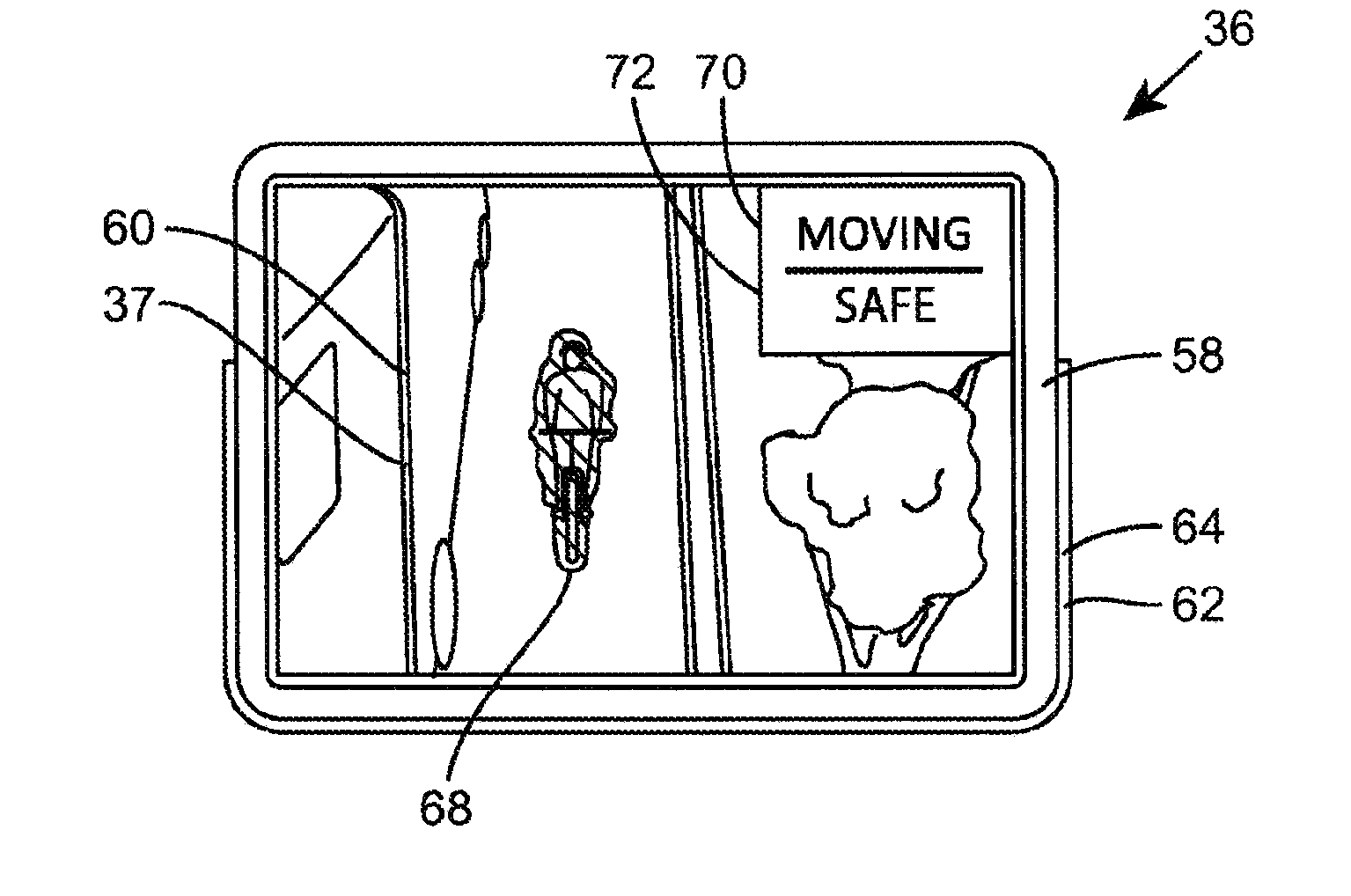
[0066]Referring now to FIG. 6, a second embodiment of a position detecting system is shown generally at 80, and comprises of first and second infra-red cameras 82, 84, the first camera being mounted at a high point on the front left-hand side of the large vehicle 12, and the second camera being mounted at a high point on the front right-hand side of the large vehicle 12. An infra-red light source is provided in each camera to flood the area surrounding the vehicle with infra red light. A reflective tag 86 is attached to the bicycle 34 and is of a distinctive shape, so that it can easily be recognised by software processing the images from the cameras 82, 84.

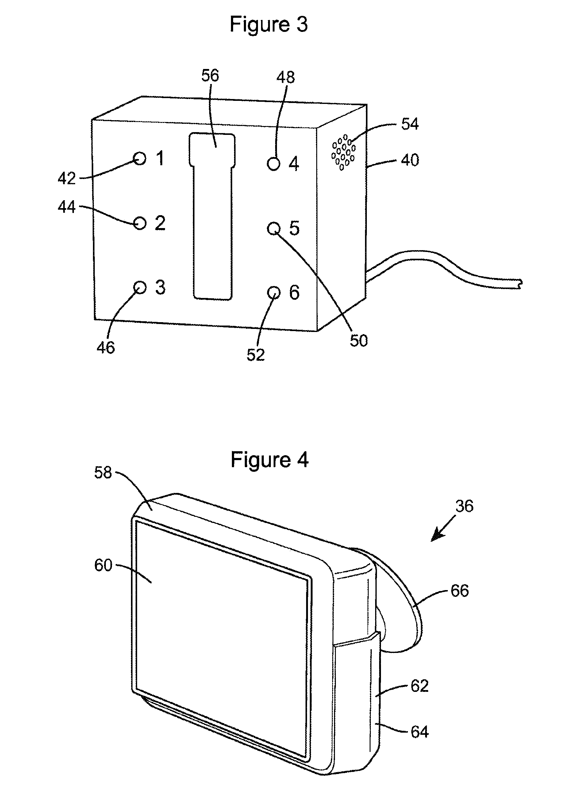
[0067]When a distinctive tag 86 is identified in the field of view of one of the cameras 82, 84, the video stream is transmitted from the camera to a video display 88 in the driver's cab.

[0068]Both the first and second embodiments described above allow a driver to be alerted to the presence of a vulnera...

embodiment

Camera-Free Embodiment

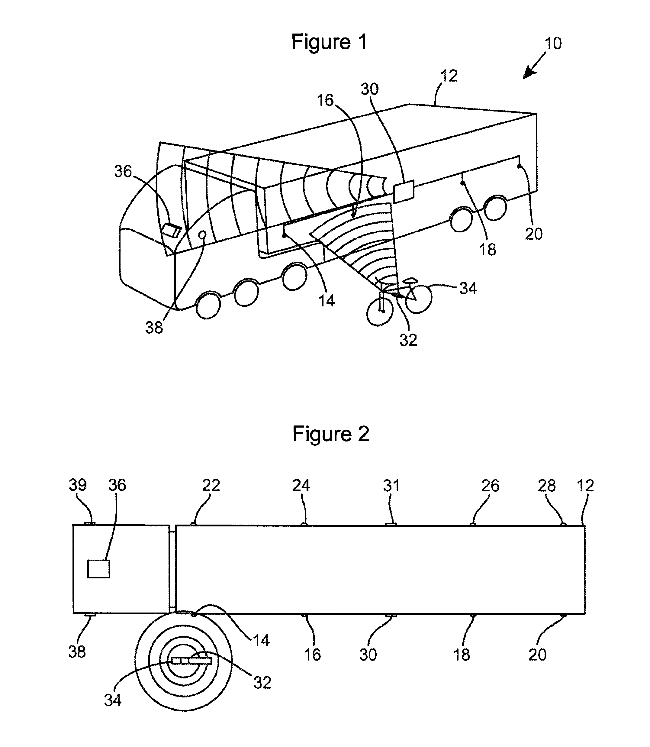
[0069]A preferred embodiment does not utilise any cameras or has the cameras of the first two embodiments switched off. In this embodiment, as before four antennas 14, 16, 18, 20 communicate wirelessly with a first receiver 30 which is mounted to the left-hand side of the large vehicle 12. A further four antennas 22, 24, 26, 28 communicate wirelessly with a second receiver 31 which is mounted to the right-hand side of the large vehicle 12. A transmitting tag 32 is attached to a bicycle 34.

[0070]When either of the first and second receivers 30, 31 receives a radio signal from the transmitting tag 32, the receiver sends a signal to a processor (not shown). The processor is able to identify which of antennas 14, 16, 18, 20 received a radio signal from the transmitter 32, and which of antennas 22, 24, 26, 28 received a radio signal from the transmitter 32. The receivers 30, 31 are able to measure the relative strength of the radio signal from each antenna, and also...


PUM


Abstract

A position detecting system 10 for installation on a large vehicle 12 comprises a detector 14 for detecting a transmitter 32 on a vulnerable vehicle such as a bicycle 34, a processor for calculating the position of the bicycle relative to the large vehicle, and a user interface 100 for providing a visual indication of said position.

Description

CLAIM OF BENEFIT AND PRIORITY FROM EARLIER FILED PATENT APPLICATIONS[0001]This application claims the benefit of and priority from International Patent Application No. PCT / GB2013 / 050823, filed Mar. 28, 2013, entitled Position Detecting System (said application designating the U.S.), and Great Britain Patent Application No. GB1205544.8, filed Mar. 29, 2012, entitled Position Detecting System, pursuant to 37 U.S.C. §371 and 37 C.F.R. §1.495. The inventor disclosed in said prior applications is the same as the inventor of the instant application, and the subject matters and disclosures of said prior applications is substantially identical to that of the instant application.FIELD OF THE INVENTION[0002]The present invention relates to a position detecting system, and particularly but not exclusively to a system for the avoidance of collisions between large vehicles and bicycles.BACKGROUND TO THE INVENTION[0003]Systems which detect the presence of bicycles in the vicinity of a large vehic...

Claims


Application Information

Patent Timeline
Patent Type & Authority Applications(United States)
IPC IPC(8): G08G1/16
CPCG08G1/16G08G1/087G08G1/163
Inventor LE MASURIER, PETER
Owner CYCLE ALERT HLDG
Why Eureka
Try Eureka