X-ray diagnostic apparatus

a diagnostic apparatus and x-ray technology, applied in the direction of instruments, radiation generation arrangements, applications, etc., can solve the problems of spot fluoroscopy not allowing real-time observation of a portion around a region, and the object is unnecessarily exposed to x-rays

Active Publication Date: 2015-03-19
TOSHIBA MEDICAL SYST CORP
View PDF2 Cites 25 Cited by
  • Summary
  • Abstract
  • Description
  • Claims
  • Application Information

AI Technical Summary

Problems solved by technology

In X-ray fluoroscopy, however, a portion around a region of interest of the object is irradiated with the same dose of X-rays as that for the region of interest, unnecessary exposure of the object to X-rays poses a problem.
However, spot fluoroscopy does not allow real-time observation of a portion around a region of interest.
In order to meet this demand, it is a challenge to develop a technique of reducing the dose of X-rays on a portion around a region of interest relative to the dose of X-rays on the region of interest.

Method used


Image

  • X-ray diagnostic apparatus
  • X-ray diagnostic apparatus
  • X-ray diagnostic apparatus

Examples


first embodiment

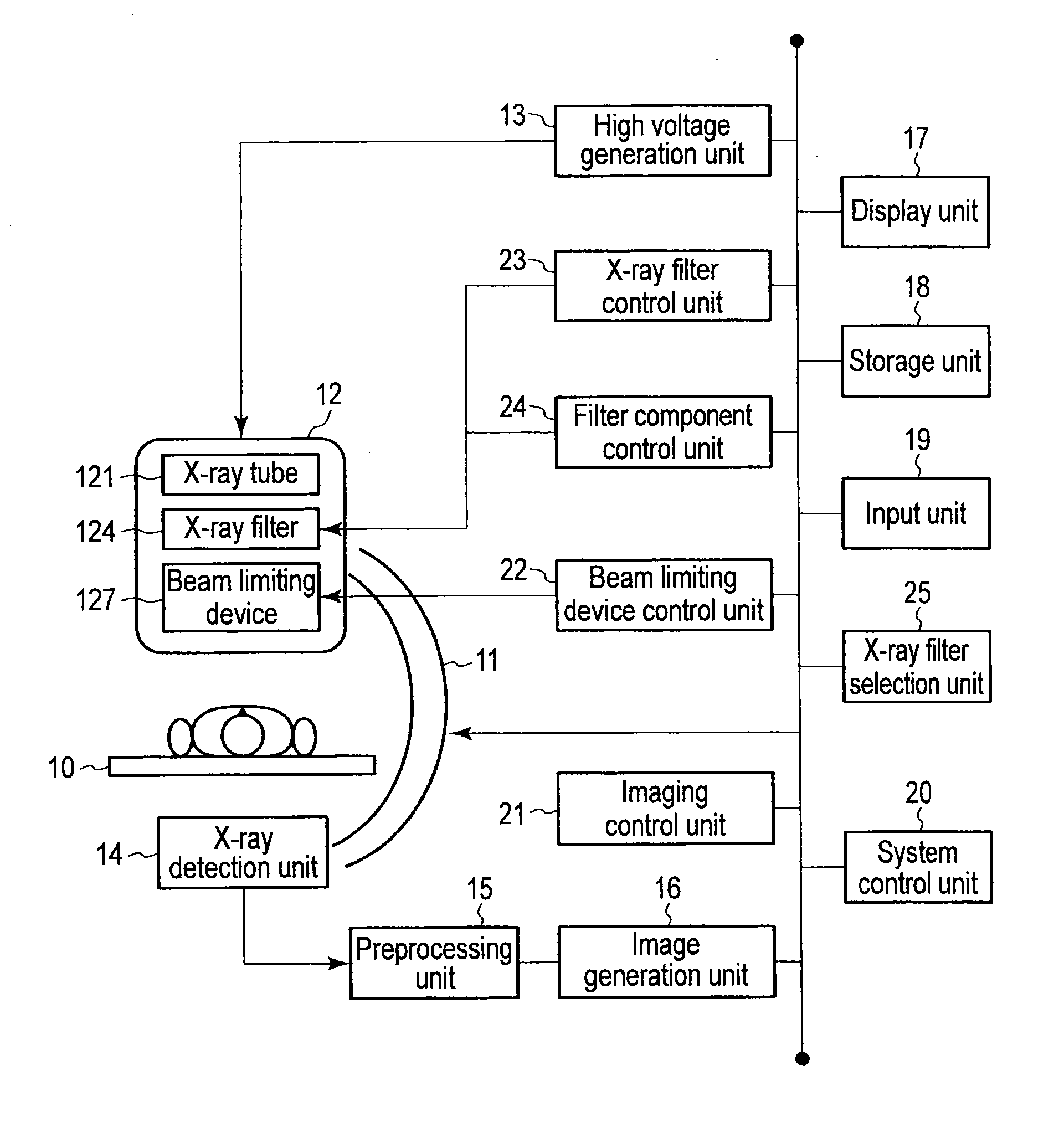
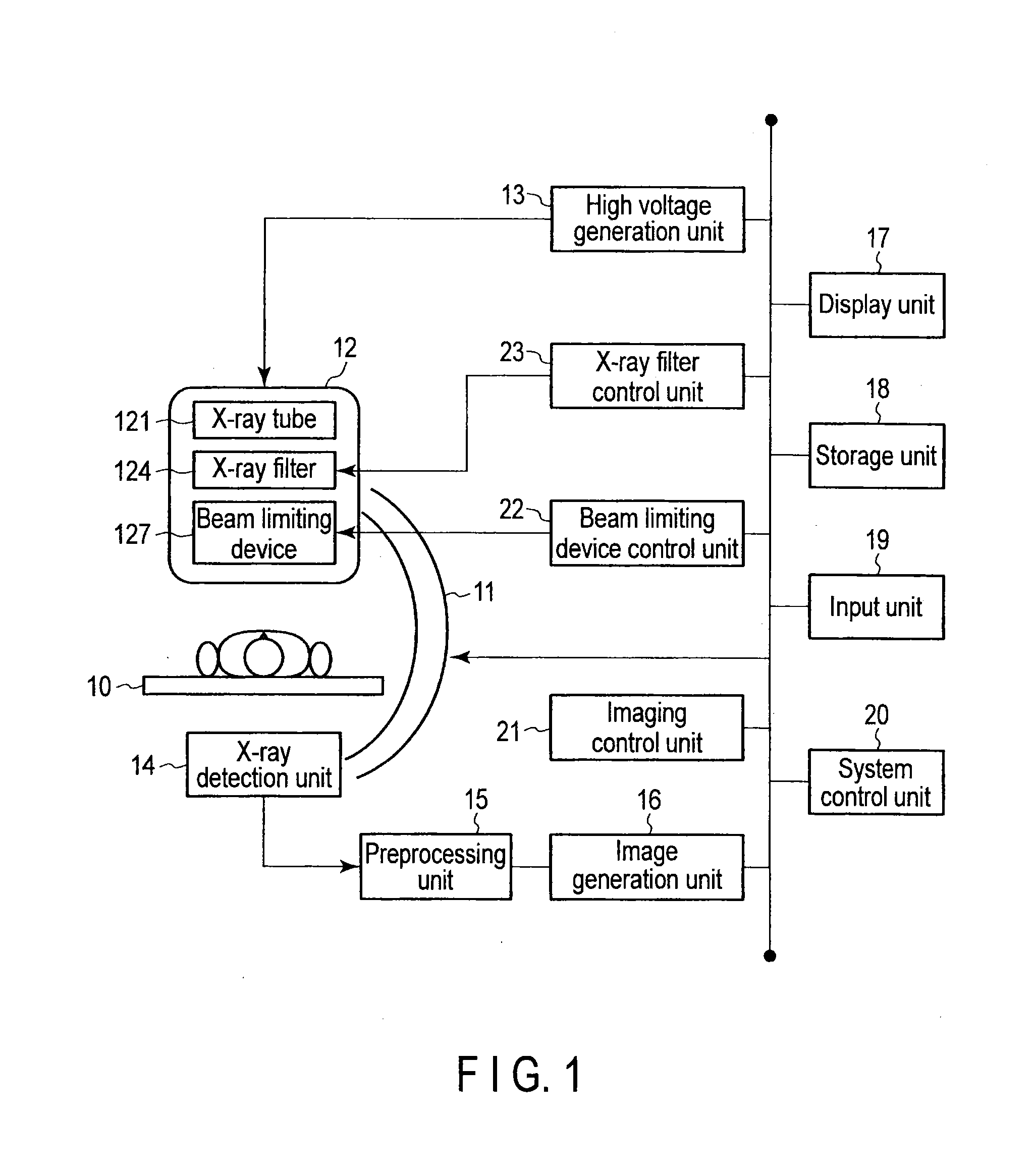
[0034]FIG. 1 is a block diagram showing the arrangement of the X-ray diagnostic apparatus according to the first embodiment. The X-ray diagnostic apparatus according to the first embodiment (to be referred to as the first X-ray diagnostic apparatus hereinafter) includes a bed 10, a C-arm 11, an X-ray irradiation system 12, a high voltage generation unit 13, an X-ray detection unit 14, a preprocessing unit 15, an image generation unit 16, a display unit 17, a storage unit 18, an input unit 19, a system control unit 20, an imaging control unit 21, a beam limiting device control unit 22, and an X-ray filter control unit 23.

[0035]The bed 10 movably supports a top (not shown) on which an object is placed. The bed 10 moves the top when a bed driving unit (not shown) is driven under the control of the system control unit 20.

[0036]The C-arm 11 is rotatably supported on a C-arm support mechanism (not shown). The C-arm support mechanism has a plurality of rotation axes for rotating the C-arm ...

second embodiment

[0074]An X-ray diagnostic apparatus (to be referred to as a second X-ray diagnostic apparatus hereinafter) according to the second embodiment differs from the first X-ray diagnostic apparatus in that it is possible to change the shape and the like of the opening of an X-ray filter 124 of the second X-ray diagnostic apparatus. The second X-ray diagnostic apparatus will be described below. Note that the second X-ray diagnostic apparatus will be described, centering on differences from the first X-ray diagnostic apparatus.

[0075]FIG. 11 is a block diagram showing the arrangement of the X-ray diagnostic apparatus according to the second embodiment. As shown in FIG. 11, the second X-ray diagnostic apparatus includes a filter component control unit 24 in addition to the constituent elements of the first X-ray diagnostic apparatus.

[0076]The filter component control unit 24 controls a filter component driving unit 128. More specifically, the filter component control unit 24 drives the filter...

third embodiment

[0094]An X-ray diagnostic apparatus according to the third embodiment differs from the first X-ray diagnostic apparatus and the X-ray diagnostic apparatus according to the second embodiment in that it can select an X-ray filter 124 with which the dose of X-rays in a high-dose range becomes a predetermined amount from a plurality of X-ray filters 124 in accordance with a user instruction, examination information of an object, patient information of the object, and the like. The third X-ray diagnostic apparatus will be described below. Note that the third X-ray diagnostic apparatus will be described, centering on differences from the first and second X-ray diagnostic apparatuses.

[0095]FIG. 16 is a block diagram showing the arrangement of the X-ray diagnostic apparatus according to the third embodiment. As shown in FIG. 16, the third X-ray diagnostic apparatus includes an X-ray filter selection unit 25 in addition to the constituent elements of the first X-ray diagnostic apparatus.

[009...


PUM


Abstract

According to one embodiment, an X-ray diagnostic apparatus includes an X-ray tube, an X-ray detector, an X-ray filter, signal input unit, and an X-ray filter support unit. The X-ray tube generates X-rays. The X-ray detector detects the X-rays transmitted through a subject. The X-ray filter is arranged between the X-ray tube and the object and having an opening. The X-ray filter support unit supports the X-ray filter so as to make the X-ray filter movable in an imaging axis direction of the X-rays.

Description

CROSS-REFERENCE TO RELATED APPLICATIONS[0001]This application is based upon and claims the benefit of priority from the prior Japanese Patent Application No. 2013-194644, filed Sep. 19, 2013 the entire contents of which are incorporated herein by reference.FIELD[0002]Embodiments described herein relate generally to an X-ray diagnostic apparatus.BACKGROUND[0003]X-ray fluoroscopy using an X-ray diagnostic apparatus is a technique of providing a user with a fluoroscopic image concerning an object, which is updated in real time. The user can observe the state of a moving organ, the manner of the flow of a contrast medium, and the like by visually recognizing the fluoroscopic image. In X-ray fluoroscopy, however, a portion around a region of interest of the object is irradiated with the same dose of X-rays as that for the region of interest, unnecessary exposure of the object to X-rays poses a problem. There is available spot fluoroscopy as a technique of suppressing such unnecessary exp...

Claims


Application Information

Patent Timeline
Patent Type & Authority Applications(United States)
IPC IPC(8): A61B6/00
CPCA61B6/4035A61B6/542A61B6/485A61B6/06A61B6/4441A61B6/487A61B6/032A61B6/40A61B6/4042A61B6/486
Inventor OHASHI, SHUMPEIKOBAYASHI, YOSHIMASAWATANABE, KOICHIRO
Owner TOSHIBA MEDICAL SYST CORP
Why Eureka
Try Eureka