Catheter assembly

a catheter and assembly technology, applied in the field of catheter assembly, can solve the problems of complex operations and exposed inner needles

Inactive Publication Date: 2015-03-19
TERUMO KK +1
View PDF3 Cites 57 Cited by
  • Summary
  • Abstract
  • Description
  • Claims
  • Application Information

AI Technical Summary

Benefits of technology

[0012]One objective of certain embodiments of the present invention is providing a catheter assembly having a structure in which, after an inner needle has been stored in a protector, the protector and a catheter hub can be separated from one another, and an operation to withdraw the inner needle can be performed with a simple operation and a small operating force.

Problems solved by technology

Therefore, in the case that such an operation is made by the user, the inner needle becomes exposed.
Further, with the aforementioned safety indwelling needle, for withdrawing and separating the inner needle from the catheter in a state in which the inner needle is protected, it is necessary to perform both a pulling-out operation and a rotating operation, and thus the operations tend to be complex.

Method used


Image

  • Catheter assembly
  • Catheter assembly
  • Catheter assembly

Examples


Embodiment Construction

[0050]Hereinafter, a preferred embodiment of a catheter assembly according to the present invention will be described in detail with reference to the accompanying drawings.

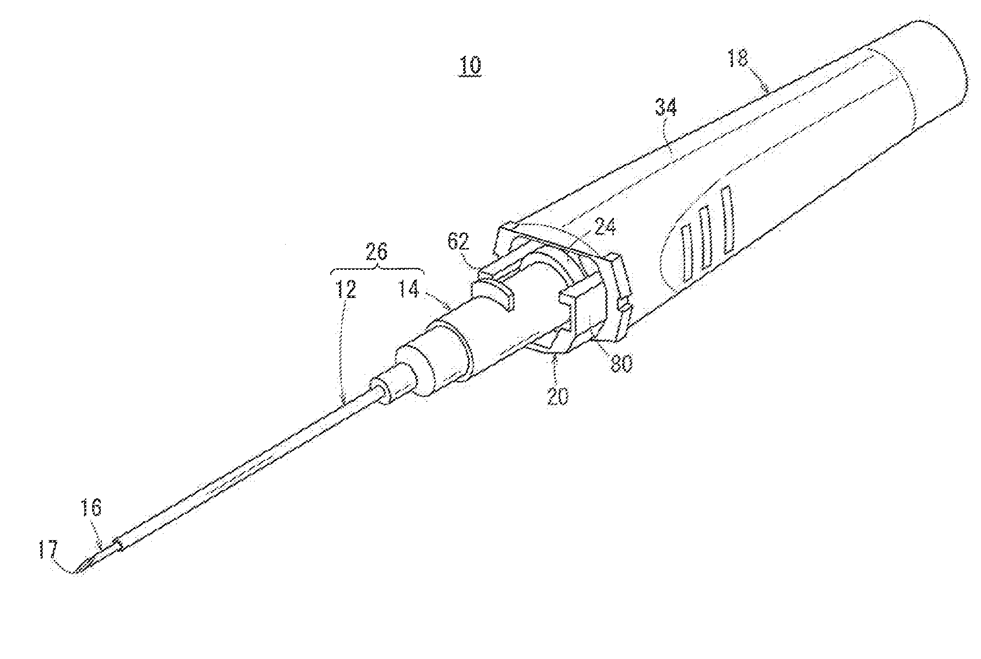
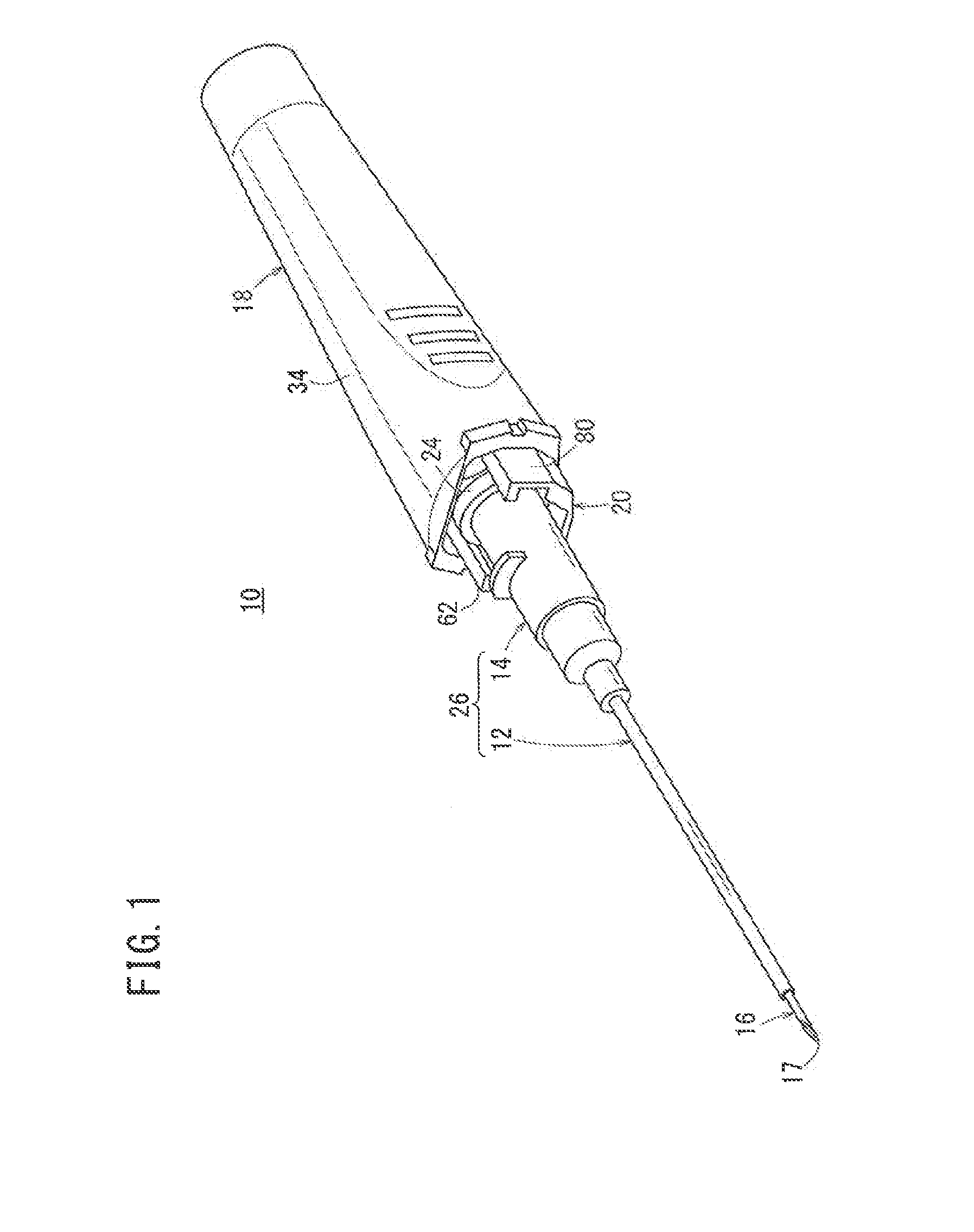
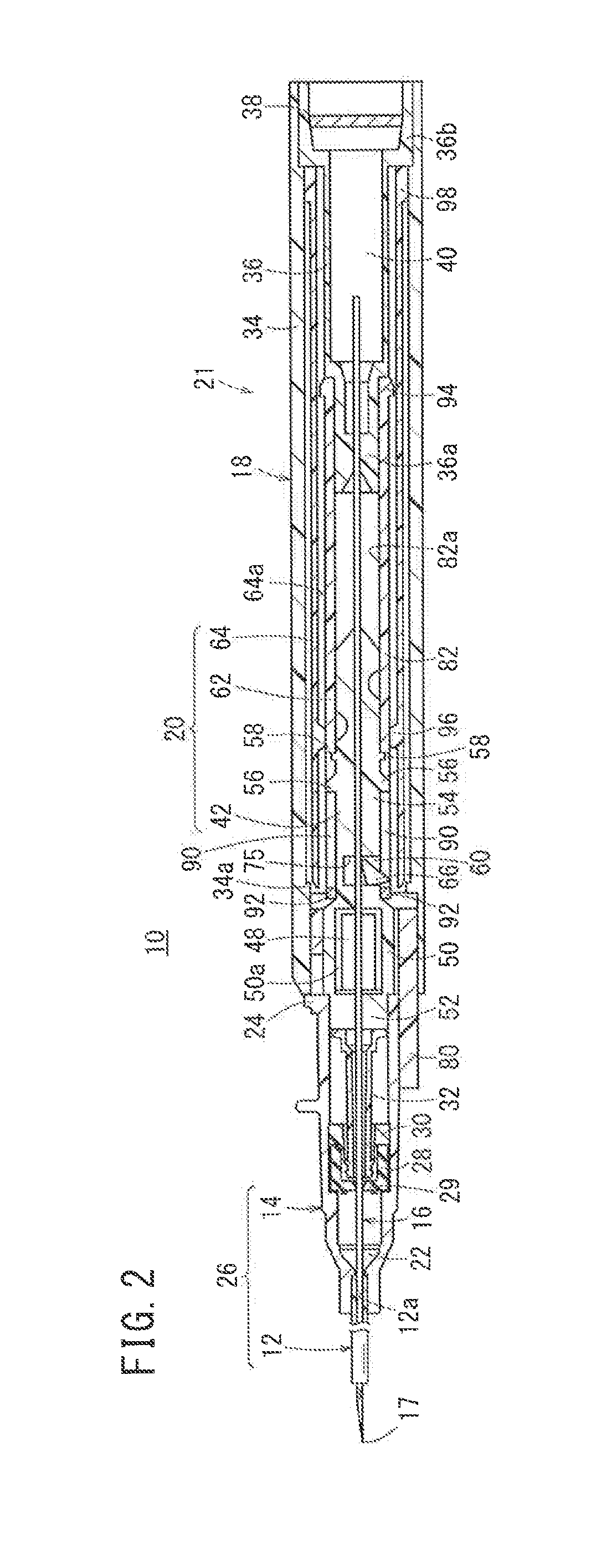
[0051]FIG. 1 is a perspective view showing the overall structure of a catheter assembly 10 according to an embodiment of the present invention. FIG. 2 is a vertical cross sectional view with partial omission of the catheter assembly 10.

[0052]As shown in FIG. 1, the catheter assembly 10 is equipped with a tubular catheter 12 that functions as an outer needle, a catheter hub 14 that is connected to a proximal end side of the catheter 12, a tubular inner needle 16 having a sharp tip 17 on a distal end thereof and which is capable of being inserted through the interior of the catheter 12, an inner needle hub 18 connected to a proximal end side of the inner needle 16, and a protector 20 that covers the tip 17 of the inner needle 16 when the inner needle 16 is retracted. The catheter assembly 10 can be used in the follo...


PUM


Abstract

A catheter assembly including: an inner needle having a sharp tip at a distal end thereof; an inner needle hub connected to a proximal end portion of the inner needle; a catheter through which the inner needle is inserted; a catheter hub connected to a proximal end portion of the catheter; and a protector that covers at least the tip of the inner needle when the inner needle is withdrawn. The protector includes: an inner tube that includes at least one arm that releasably engages with a proximal end of the catheter hub from an outer side of the catheter hub; and an outer tube inside which the inner tube is arranged, and which is capable of being displaced in an axial direction relative to the inner tube. The catheter assembly is configured such that, when the inner needle is withdrawn, after the tip of the inner needle has been stored in the protector, the outer tube is retracted with respect to the inner tube thereby allowing the at least one arm to be displaced outwardly, whereby engagement between the at least one arm and the catheter hub is released.

Description

CROSS-REFERENCE TO RELATED APPLICATIONS[0001]This application is a continuation application filed under 35 U.S.C. 111(a) claiming the benefit under 35 U.S.C. §§120 and 365(c) of PCT International Application No. PCT / JP2012 / 062451 filed on May 16, 2012, the contents of which is hereby incorporated by reference in its entirety.BACKGROUND[0002]1. Technical Field[0003]The present disclosure relates to a catheter assembly that can puncture and remain indwelled in a blood vessel, for example, when performing an infusion on a patient.[0004]2. Background Art[0005]Conventionally, when an infusion is carried out on a patient, a catheter assembly has been used. This type of catheter assembly is equipped with a hollow outer needle (catheter), an outer needle hub (catheter hub) that is fixed to a proximal end of the outer needle, an inner needle that is inserted into the outer needle and has a sharp tip at a distal end thereof, and an inner needle hub that is fixed to a proximal end of the inner...

Claims


Application Information

Patent Timeline
Patent Type & Authority Applications(United States)
IPC IPC(8): A61M25/06
CPCA61M25/0631A61M2205/7536A61M2025/0018A61M25/0606A61M5/3243A61M25/0693A61M2005/325
Inventor TANABE, HIDENORIZUSHI, YASUNOBU
Owner TERUMO KK
Why Eureka
Try Eureka