

Motorcycle
a technology for motorcycles and parts, applied in the field of motorcycles, can solve the problems of reducing the intake efficiency and being difficult to deal with this type of demand within a narrow space, and achieve the effect of effective arrangement structure of parts
- Summary
- Abstract
- Description
- Claims
- Application Information
AI Technical Summary
Benefits of technology
Problems solved by technology
Method used
Image

Examples
first embodiment
[0048]Hereinafter, preferred embodiments of a motorcycle of the present invention will be described based on the drawings.
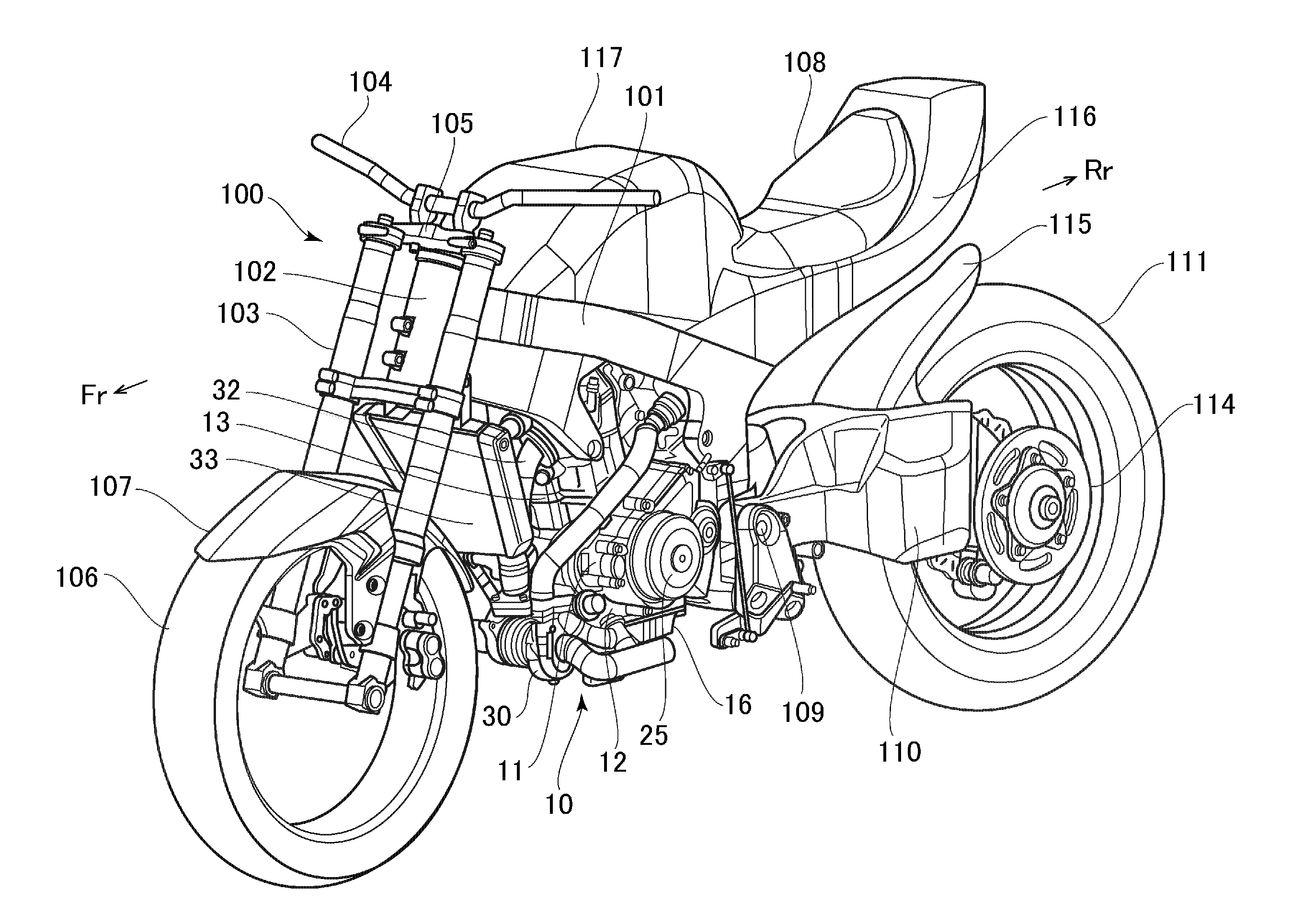
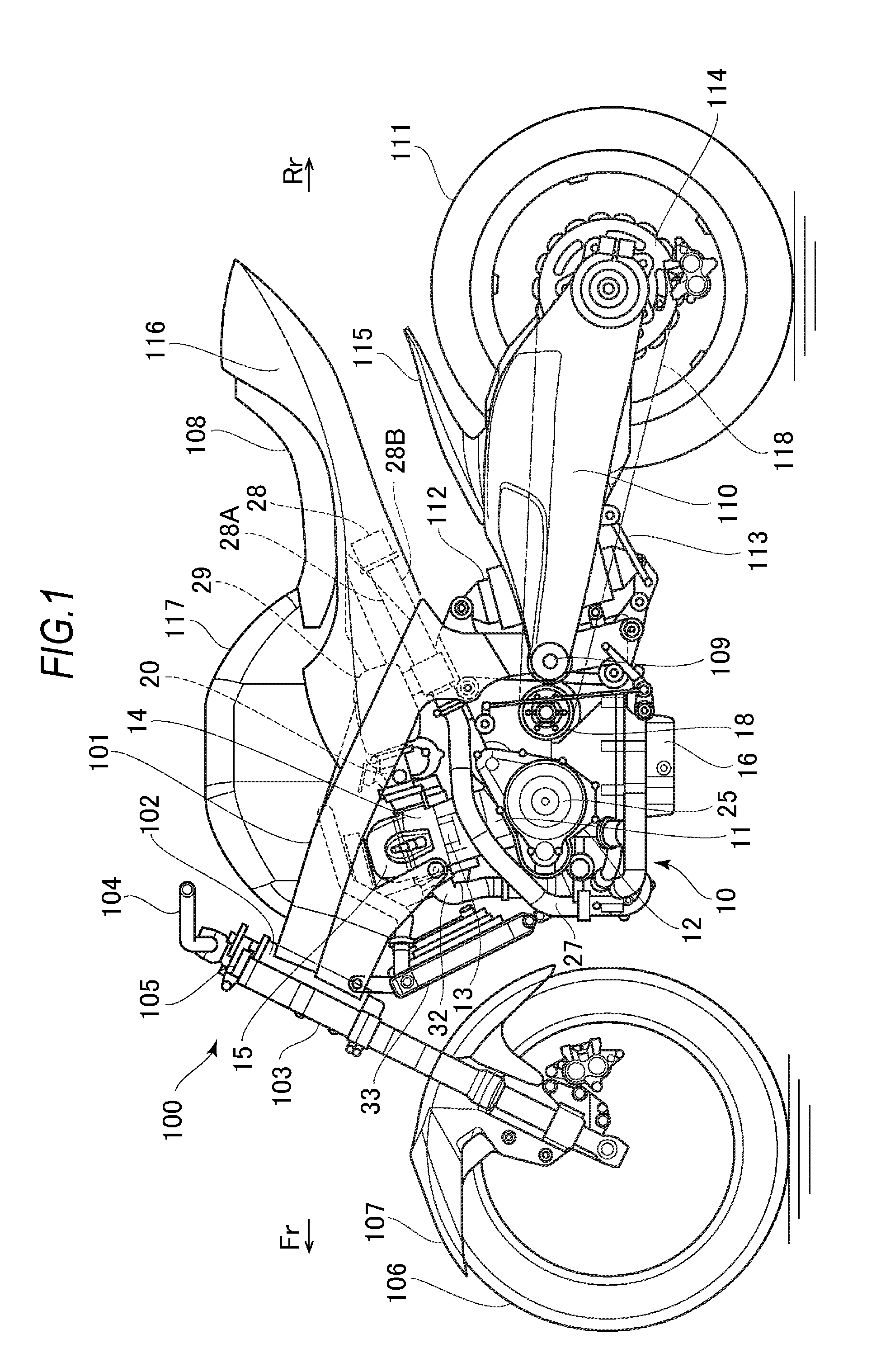
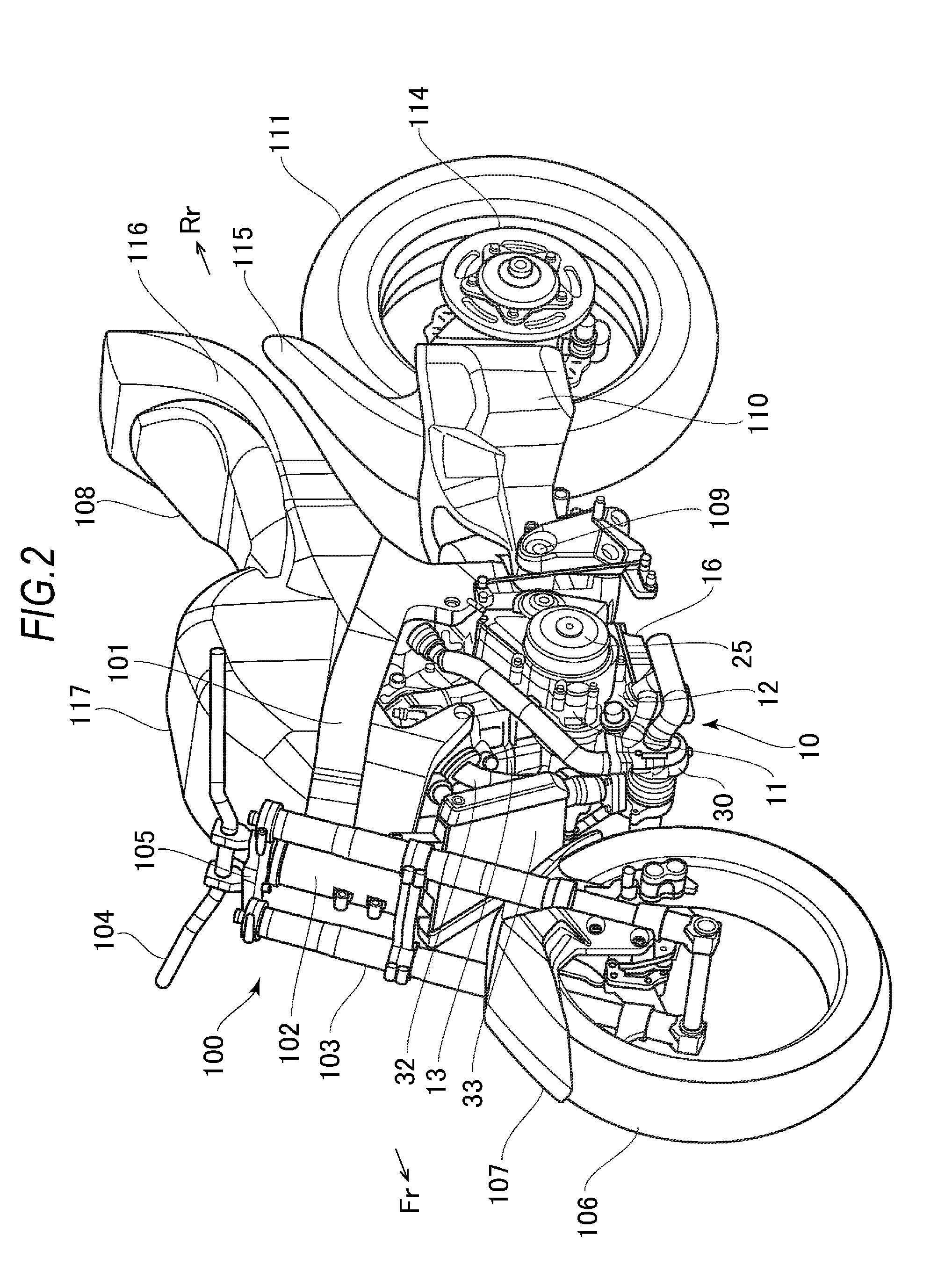
[0049]FIG. 1 to FIG. 3 illustrate a schematic configuration of a motorcycle 100 as an application example of the present invention, in which FIG. 1 is a side view, FIG. 2 is a perspective view when seen from the front side, and FIG. 3 is a perspective view when seen from the rear side. First, the entire configuration of the motorcycle 100 will be described by using these drawings. Note that in the drawings used in the following description including FIG. 1 to FIG. 3, a front side, a rear side, a lateral right side, and a lateral left side of a vehicle are indicated by an arrow mark Fr, an arrow mark Rr, an arrow mark R, and an arrow mark L, respectively, according to need.
[0050]In FIG. 1 to FIG. 3, on front portions of vehicle body frames 101 (main frames) made of steel or aluminum alloy material, there are provided two right and left front forks 103 supported to...
second embodiment
[0082]Next, a motorcycle of a second embodiment will be described. A supercharging system of an internal combustion engine of the present embodiment is different from that of the first embodiment. Hereinafter, the supercharging system of the present embodiment will be described with reference to FIG. 13 to FIG. 20. FIG. 13 is a side view of a periphery of an engine unit. FIG. 14 is a top view of the periphery of the engine unit. FIG. 15 is a perspective view of a periphery of an intake system of the engine unit. FIG. 16 is a left side view of an engine including the periphery of the intake system. FIG. 17 is a top view of the engine including the periphery of the intake system. FIG. 18 is a view schematically illustrating a flow path of intake air in the intake system. FIG. 19 is a perspective view illustrating a main configuration of the supercharging system. FIG. 20 is a schematic view illustrating the main configuration of the supercharging system. Note that the configuration sam...
third embodiment
[0094]Next, a motorcycle of a third embodiment will be described. A cooling structure of an intercooler of the present embodiment is different from that of the first and second embodiments. Hereinafter, the cooling structure of the intercooler of the present embodiment will be described while referring to FIG. 23 to FIG. 34. FIG. 23 is a side view of the motorcycle. FIG. 24 is a perspective view of the motorcycle when seen from the rear side. FIG. 25 is a perspective view of a periphery of an engine unit. FIG. 26 is a top view of the engine unit. FIG. 27 is a perspective view of the intercooler. Note that the configuration same as that of the first embodiment is denoted by the same reference numeral, and explanation thereof will be omitted.
[0095]As illustrated in FIG. 23, a front portion of a vehicle body of the motorcycle of the present embodiment is covered by a front cowling 124. The front cowling 124 is attached, via the vehicle body frames 101 and the like, at a position above ...
PUM
 Abstract
Description
Claims
Application Information