Tube-in-tube LED tube

Inactive Publication Date: 2015-03-26
DONGGUAN CITY SAIGANG DECORATION MATERIAL
View PDF10 Cites 6 Cited by
  • Summary
  • Abstract
  • Description
  • Claims
  • Application Information

AI Technical Summary

Benefits of technology

The invention provides a tube-in-tube LED tube that solves the problems of traditional LED lamps. It has good insulation, high safety, uniform illumination, larger illumination range, simple structure, and easy to manufacture and maintenance. The LED lamp board is embedded into the slots in the inner wall of the tubular plastic lampshade, resulting in convenient and quickly installation, and material saving. The tubular plastic lampshade can still protect the LED lamp board from being damaged in case of the glass tube broken.

Problems solved by technology

The traditional fluorescent lamps are filled with phosphor containing heave metals, that may pollute the environment and cause great harm to the human body in the manufacturing process and use.
In addition, the fluorescent lamps can not meet human's requirement because of their large power consumption and short service life.
LED component is a point light source, a number of the LED components are normally mounted on a circuit board to form luminous strip for lighting in the use of the process to achieve the luminous effect enough, but the light irradiated out is not uniform, easy to dizziness causing visual fatigue.
China patent 201220486312.4 discloses a model of LED glass tube, the LED glass tube with irregular circular cross section opens a notch in the inner wall of the tube, the notch is used to install a LED lamp board, the light irradiated out is not uniform and easy to dizziness.

Method used


Image

  • Tube-in-tube LED tube
  • Tube-in-tube LED tube
  • Tube-in-tube LED tube

Examples


first embodiment

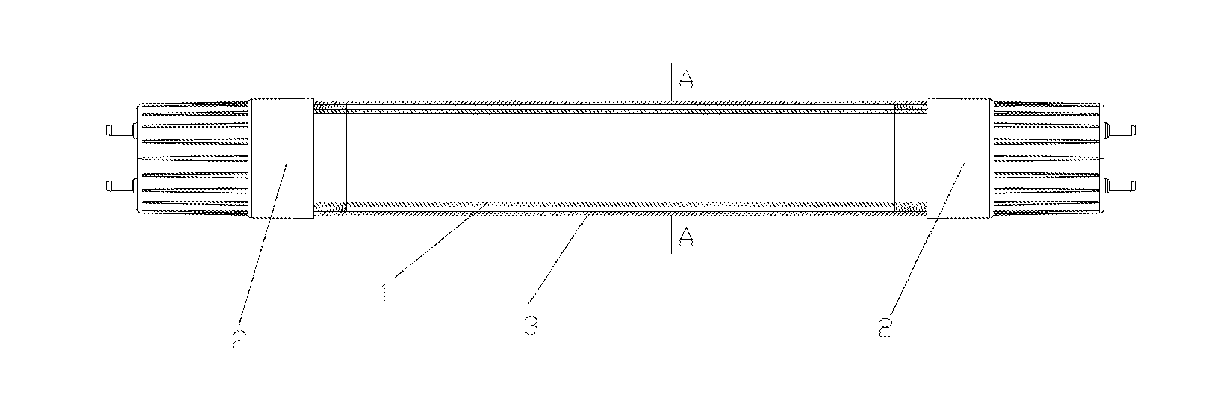
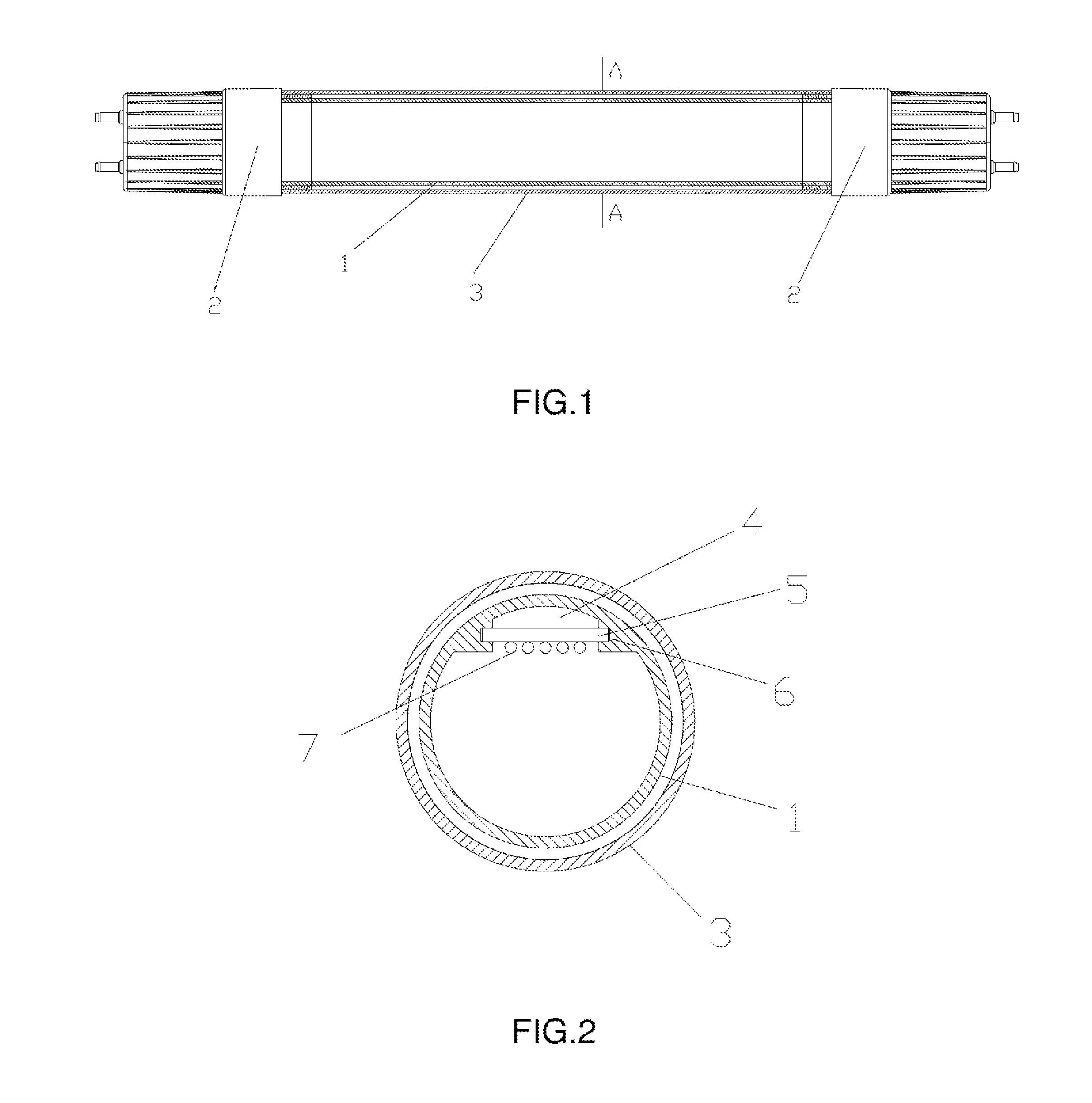
[0014]FIG. 1 and FIG. 2 show a tube-in-tube LED tube in accordance with the invention. The tube-in-tube LED tube comprises a tubular plastic lampshade 1, two caps 2 connected to power supply are separately defined at the two ends of the tubular plastic lampshade 1, the tubular plastic lampshade 1 is sheathed with a glass tube 3 and two ends of the glass. tube 3 are separately connected to the two caps 2. The tubular plastic lampshade 1 is an integral forming structure. Two symmetrical slots 6 are defined in the inner wall of the tubular plastic lampshade 1 longitudinally. Two side edges of LED lamp board 5 are separately inserted in the two slots 6. A gap 4 is formed between the bottom of LED lamp board 5 and the inner wall of the tubular plastic lampshade 1.

second embodiment

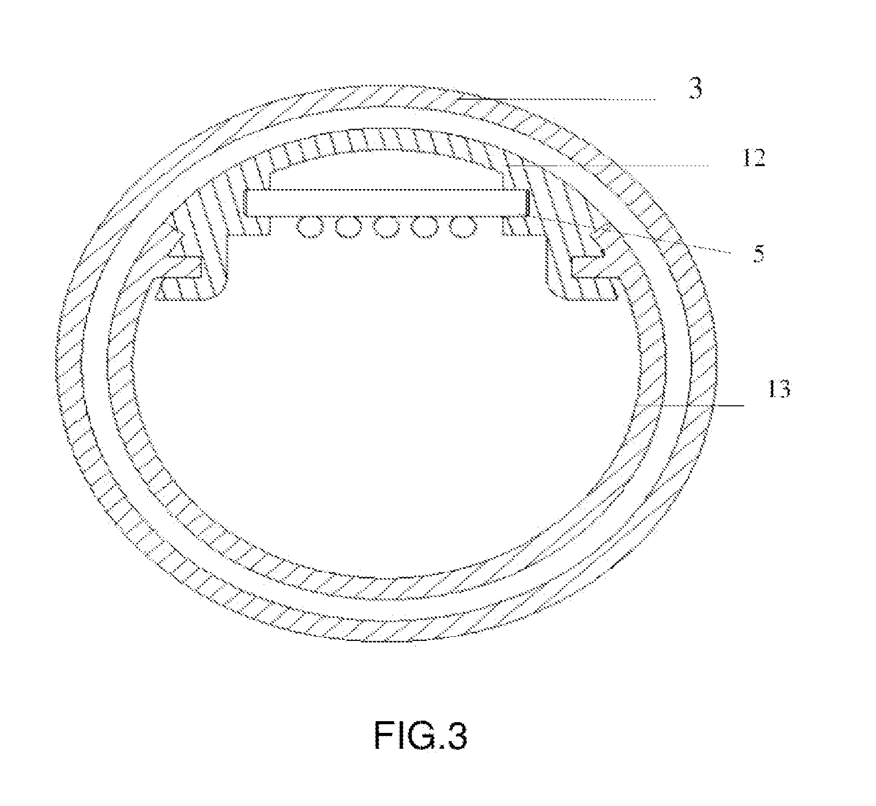
[0015]FIG. 3 shows a circular tubular plastic lampshade formed by an arc plastic parts 13 connected with an arc metal parts 12 by way of insertion in accordance with the invention. Two symmetrical slots are defined in the inner wall of the arc metal parts 12 longitudinally. Two side edges of LED lamp board 5 are separately inserted in the two slots. A gap is formed between the bottom of LED lamp board 5 and the inner wall of the arc metal parts 12.

[0016]Wherein, the gap between the tubular plastic lampshade 1 and glass tube 3 is 1 mm. The gap can protect the LED lamp board from being damaged. In case of the glass tube broken, the tubular plastic lampshade can still protect the LED lamp board from being damaged and there is high safety for the LED lamp board.

[0017]In accordance with the embodiment of the invention some optimal values can be selected from as following: the outer diameter of the glass tube 3 is 26 mm and the thickness of the glass tube 3 is 1 mm; the outer diameter of ...


PUM


Abstract

The invention relates to a tube-in-tube LED tube, which comprises a tubular plastic lampshade, two caps connected to power supply is separately defined at the two ends of the tubular plastic lampshade, a LED lamp board is defined inside the tubular plastic lampshade sheathed with a glass tube and two ends of the glass tube is separately connected to the two caps. In case of the glass tube broken, the tubular plastic lampshade can still protect the LED lamp board from being damaged. By the way, the tube-in-tube LED tube has properties of high safety, uniform illumination, larger illumination range, simple structure, and easy to manufacture and maintenance. Also the LED lamp board is embedded into the slots in the inner wall of the tubular plastic lampshade, resulting in convenient and quickly installation, and material saving.

Description

BACKGROUND OF THE INVENTION[0001]The present invention relates to lamps and, in particular, to a tube-in-tube LED tube.[0002]Lamps are widely used in different objects, such as in homes, offices and industry, and they are necessary in our daily life. The traditional fluorescent lamps are filled with phosphor containing heave metals, that may pollute the environment and cause great harm to the human body in the manufacturing process and use. In addition, the fluorescent lamps can not meet human's requirement because of their large power consumption and short service life. It is a good idea to replace the fluorescent lamps with LED tubes having energy saving, environmental protection and long service life.[0003]LED component is a point light source, a number of the LED components are normally mounted on a circuit board to form luminous strip for lighting in the use of the process to achieve the luminous effect enough, but the light irradiated out is not uniform, easy to dizziness caus...

Claims


Application Information

Patent Timeline
IPC IPC(8): F21K99/00F21V3/02F21V3/04
CPCF21Y2103/003F21K9/175F21K9/27F21Y2103/10F21Y2115/10
Inventor HUANG, CHAORONG
Owner DONGGUAN CITY SAIGANG DECORATION MATERIAL
Why Eureka
Try Eureka