Adjustable friction joint assembly for crash test dummy

a friction joint and dummy technology, applied in the field of crash test dummies, can solve the problems of loosening and over-tightening of new operators, and achieve the effect of increasing sensitivity and loosening of joints

Active Publication Date: 2015-03-26
HUMANETICS INNOVATIVE SOLUTIONS
View PDF2 Cites 17 Cited by
  • Summary
  • Abstract
  • Description
  • Claims
  • Application Information

AI Technical Summary

Benefits of technology

[0012]One advantage of the present invention is that a new adjustable friction joint assembly is provided for a crash test dummy. Another advantage of the present invention is that the adjustable friction joint assembly provides increased sensitivity with respect to a tightness of the joint. Yet another advantage of the present invention is that the adjustable friction joint assembly provides a visual feedback to approximately locate a “1 g” setting. Still another advantage of the present invention is that the adjustable friction joint assembly provides resistance to loosening by pins. Still another advantage of the present invention is that the adjustable friction joint assembly is a mechanical adjustment for adjusting a tightness of the joint on a crash test dummy. A further advantage of the present invention is that the adjustable friction joint assembly provides friction adjustment for tightness of the joint on a crash test dummy. Still a further advantage of the present invention is that the adjustable friction joint assembly can be used not only for the knee joint, but can be used for other joints of the crash test dummy. Yet still a further advantage of the present invention is that the adjustable friction joint assembly provides for loosening of the joint during setup by the addition of pins which prevent relative rotation between a tapped hole (center of the joint) and friction adjustment, and a top plate giving visual feedback as to the tightness of the joint when its top face is flush with the top face of a housing.

Problems solved by technology

One disadvantage of a current joint is that the only indicator as to the tightness is operator feel, leading to novice operators frequently over tightening.
Another disadvantage of the current joint is that it has a very small contact area to generate friction and can loosen with movement of the joint.
Yet another disadvantage of the current joint is that it only applies to a particular type of joint such as a knee joint of a crash test dummy.

Method used


Image

  • Adjustable friction joint assembly for crash test dummy
  • Adjustable friction joint assembly for crash test dummy
  • Adjustable friction joint assembly for crash test dummy

Examples


Embodiment Construction

)

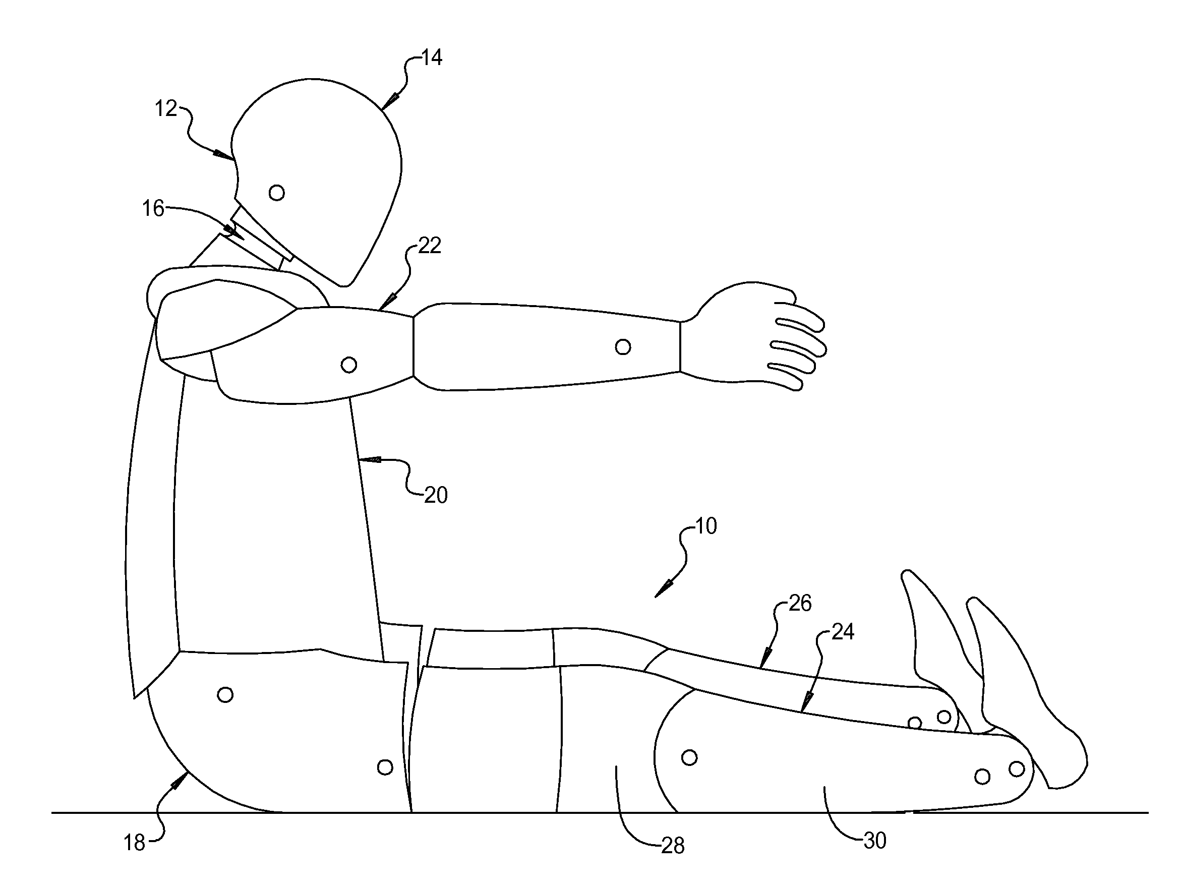
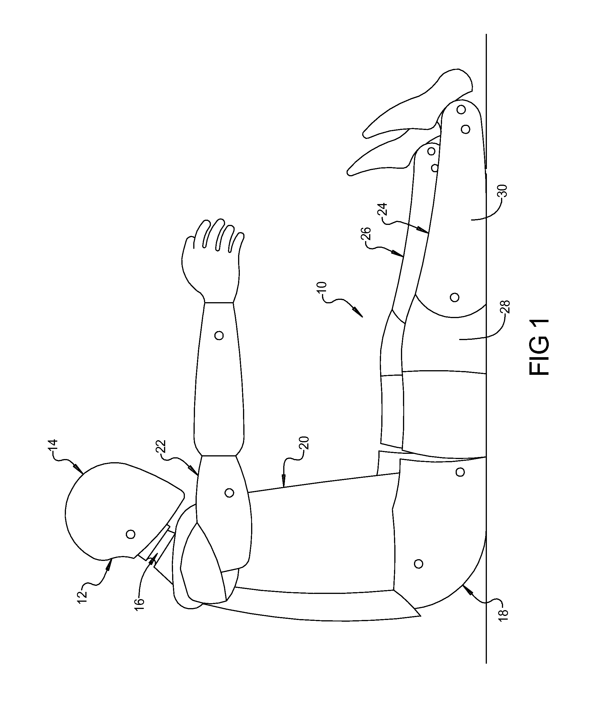
[0027]Referring to the drawings and in particular FIGS. 1 and 2, one embodiment of an adjustable friction joint assembly 10, according to the present invention, is shown in operational relationship with a crash test dummy, generally indicated at 12. The crash test dummy 12 is of a fiftieth percentile (50%) male type and is illustrated in a sitting position. This crash test dummy 12 is used primarily to test the performance of automotive interiors and restraint systems for adult front and rear seat occupants. The size and weight of the crash test dummy 12 are based on anthropometric studies, which are typically done separately by the following organizations, University of Michigan Transportation Research Institute (UMTRI), U.S. Military Anthropometry Survey (ANSUR), and Civilian American and European Surface Anthropometry Resource (CESAR). It should be appreciated that ranges of motions, centers of gravity, and segment masses simulate those of human subjects defined by the anthropom...


PUM


Abstract

An adjustable friction joint assembly for a crash test dummy includes a first joint member for connection to a first member of the crash test dummy and a second joint member for connection to a second member of the crash test dummy. The adjustable friction joint assembly also includes a shaft operatively connected to the first joint member and the second joint member to allow rotation therebetween. The adjustable friction joint assembly further includes an adjustable friction assembly operatively connected to the shaft and operatively cooperating with the first joint member and the second joint member to adjust a friction tightness of the joint assembly.

Description

CROSS-REFERENCE TO RELATED APPLICATION(S)[0001]The present invention claims the priority date of co-pending U.S. Provisional Patent Application Ser. No. 61 / 882,466, filed Sep. 25, 2013.GOVERNMENT RIGHTS IN THE INVENTION[0002]The invention was made with government support under Government contract number W911QX-12-C-0015 awarded by the Department of the Army. The government has certain rights in the invention.BACKGROUND OF THE INVENTION[0003]1. Field of the Invention[0004]The present invention relates generally to crash test dummies and, more particularly, to an adjustable friction joint assembly for a crash test dummy.[0005]2. Description of the Related Art[0006]Automotive, aviation, and other vehicle manufacturers conduct a wide variety of collision testing to measure the effects of a collision on a vehicle and its occupants. Through collision testing, a vehicle manufacturer gains valuable information that can be used to improve the vehicle.[0007]Collision testing often involves th...

Claims


Application Information

Patent Timeline
Patent Type & Authority Applications(United States)
IPC IPC(8): G09B23/32
CPCG09B23/32Y10T403/32418
Inventor GIBBS, JOSEPHWANG, ZHENWEN J.
Owner HUMANETICS INNOVATIVE SOLUTIONS
Why Eureka
Try Eureka