
Chest Compression Device

a chest compression and chest compression technology, applied in the field of chest compression devices for cardiopulmonary resuscitation (cpr) and chest compression, can solve the problems of lateral spreading of the thorax and the effectiveness of automated chest compressions

Active Publication Date: 2015-04-02
ZOLL CIRCULATION
View PDF5 Cites 12 Cited by
  • Summary
  • Abstract
  • Description
  • Claims
  • Application Information

AI Technical Summary

Benefits of technology

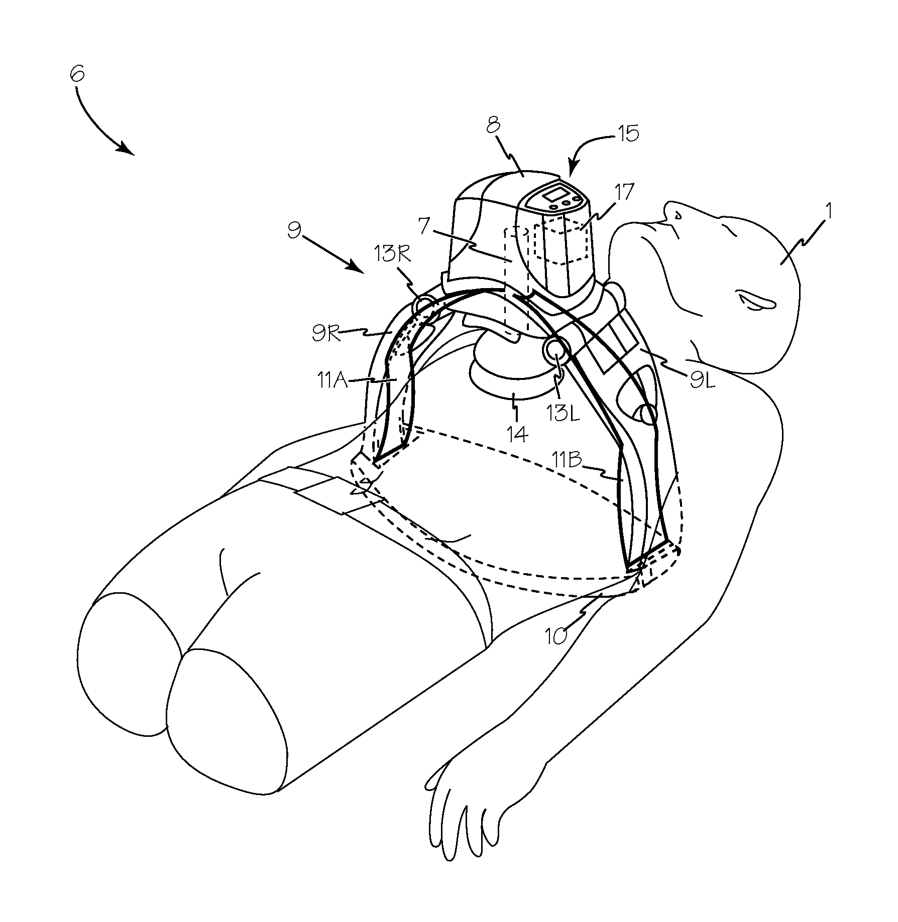
The chest compression device described in this patent uses a piston to compress the sternum and leaf springs to apply lateral compression to the chest during compressions. The device is powered by a motor and can provide therapeutic compressions by extending and contracting the piston. The leaf springs are connected to the piston and the device base or support leg, so when the piston is extended, the springs are compressed against the base or leg, providing additional compression to the patient's chest. This device can provide better compression and can be used in combination with other medical devices.

Problems solved by technology

As mechanical compressions are performed by piston-based chest compression systems, the patient's rib cage hinges or shifts about the sternum resulting in lateral spreading of the thorax and the effectiveness of the automated chest compressions are diminished.

Method used


Image

  • Chest Compression Device
  • Chest Compression Device
  • Chest Compression Device

Examples


Embodiment Construction

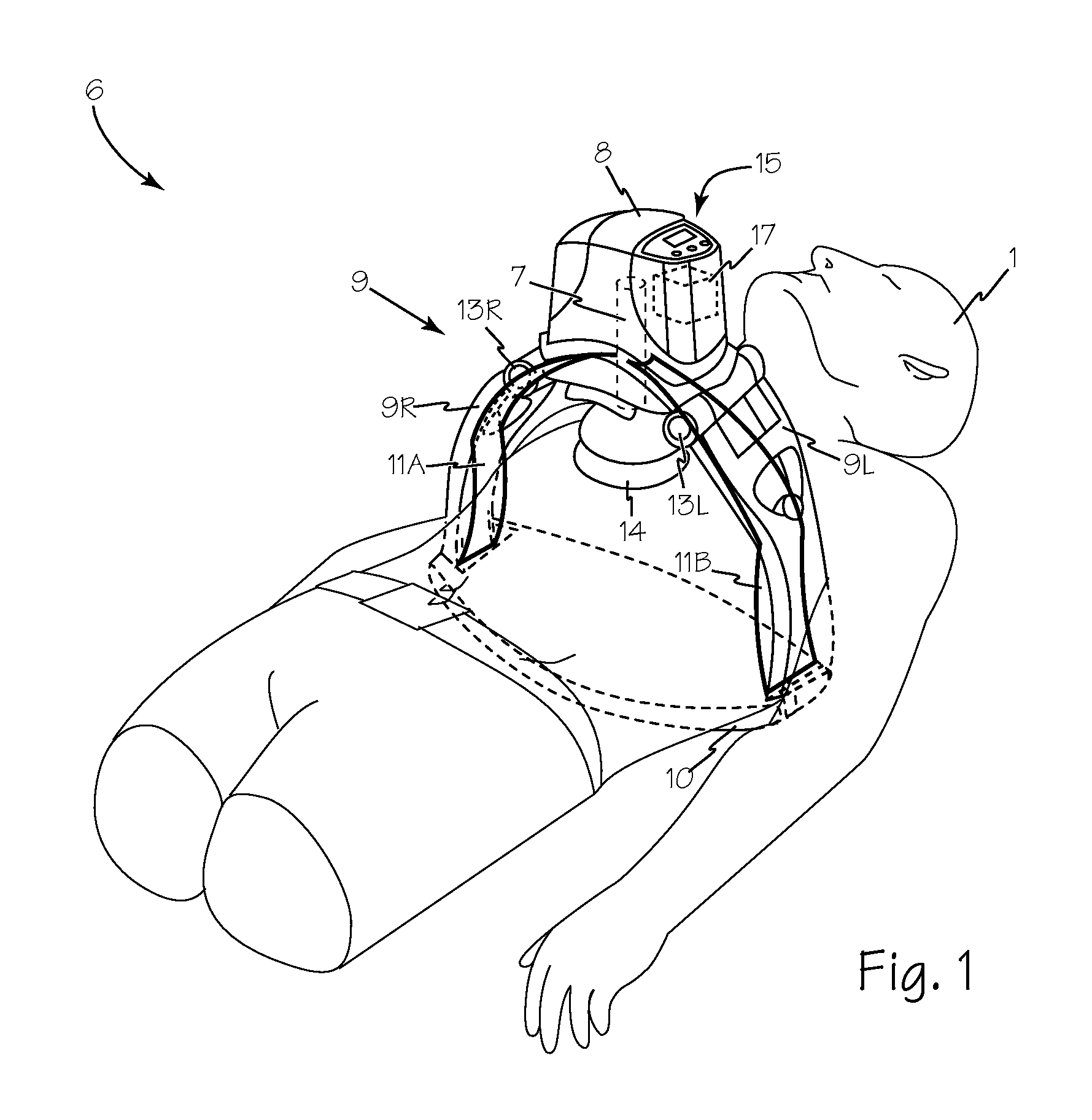
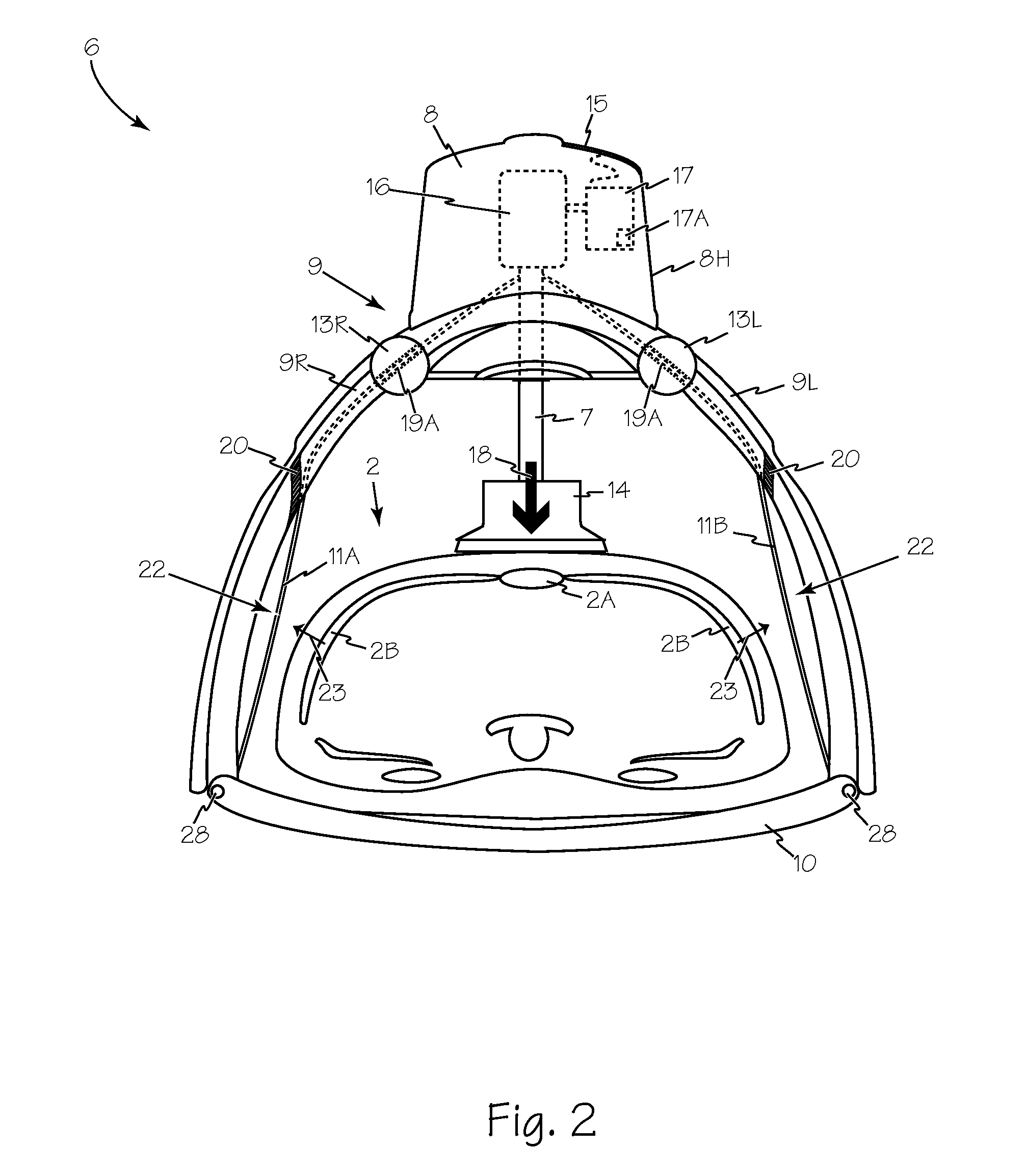
[0014]FIGS. 1 illustrates the chest compression device fitted on a patient 1. The chest compression device 6 applies compressions with the piston 7. The piston is disposed within compression unit 8 which is supported over the patient with a frame or gantry 9 having two legs 9L and 9R fixed to a backboard 10. Compression unit 8 is connected to legs 9L and 9R at hinges 13R and 13L. Leaf springs 11A and 11B are operably connected between piston 7 and either backboard 10 or to support legs 9L and 9R through hinges 13R and 13L. Springs 11A and 11B may be formed of a single layer of material or they may be formed of two or more layers or two or more parallel springs.

[0015]When disposed about the patient, the frame extends over thorax 2 of the patient so that the piston is disposed apposing sternum 2A to contact the patient's chest directly over the sternum, to impart compressive force on the sternum of the patient as shown in FIG. 2. Piston 7 may include a removable compression pad 14 ada...


PUM


Abstract

A chest compression device includes a piston to apply compression to the sternum and incorporates leaf springs simultaneously driven by the piston to apply lateral compression to the thorax during chest compressions. A motor in the chest compression device provides motive power to cyclically extend and contract the piston to provide therapeutic chest compressions. One end of each leaf spring is operably connected to the piston and the other end of each leaf spring is secured to the backboard / base or to a support leg of the chest compression device such that during extension of the piston, each leaf spring is compressed against the device base or leg which causes the springs to flex and provide lateral compression of the patient's thorax in addition to the sternal compression of the piston.

Description

Field of the Inventions[0001]The inventions described below relate to the field of cardiopulmonary resuscitation (CPR) chest compression devices.BACKGROUND OF THE INVENTIONS[0002]Cardiopulmonary resuscitation (CPR) is a well-known and valuable method of first aid used to resuscitate people who have suffered from cardiac arrest. CPR requires repetitive chest compressions to squeeze the heart and the thoracic cavity to pump blood through the body. Artificial respiration, such as mouth-to-mouth breathing or bag mask respiration, is used to supply air to the lungs. When a first aid provider performs manual chest compression effectively, blood flow in the body is about 25% to 30% of normal blood flow.[0003]In efforts to provide better blood flow and increase the effectiveness of bystander resuscitation efforts, various mechanical devices have been proposed for performing CPR. Among the variations are pneumatic vests, hydraulic and electric piston devices as well as manual and automatic b...

Claims


Application Information

Patent Timeline
IPC IPC(8): A61H31/00
CPCA61H31/006A61H2201/1215A61H2201/1664A61H2201/1207A61H2201/5043
Inventor ILLINDALA, UDAY KIRAN V.
Owner ZOLL CIRCULATION
Learn More