
Rotary catheter drive unit containing seal-sets

a technology of sealing set and drive unit, which is applied in the field of catheters, can solve the problems of forcing patients to undergo a more formidable bypass surgery, and achieve the effect of reducing the likelihood of releasing particles and ensuring aspiration

Inactive Publication Date: 2015-04-02
SHIBER SAMUEL
View PDF2 Cites 21 Cited by
  • Summary
  • Abstract
  • Description
  • Claims
  • Application Information

AI Technical Summary

Benefits of technology

The present invention is a rotary catheter with a narrow tip designed to mechanically break down obstacles in blood vessels. The tip has sides that bluntly impact the obstruction to break it down. The catheter has a flexible hollow shaft with passages that deliver cooling and lubricating fluid to the impact site and allow the particles to be aspirated. The tip has a smooth rounded distal end that can fit over a guidewire and slide through narrow passages. The catheter can be advanced through a total obstruction and can be used in conjunction with a guiding catheter or embolic protection device. The flexible hollow shaft prevents kinking and sharp bending of the catheter. The rotary catheter can be made in different lengths and diameters for different anatomical locations and forms of obstructions.

Problems solved by technology

Total occlusions often prevent advancement of a guidewire and thereby prevent the delivery of percutaneous trans-catheter treatment, forcing a patient to undergo a more formidable bypass surgery.

Method used


Image

  • Rotary catheter drive unit containing seal-sets
  • Rotary catheter drive unit containing seal-sets
  • Rotary catheter drive unit containing seal-sets

Examples


Embodiment Construction

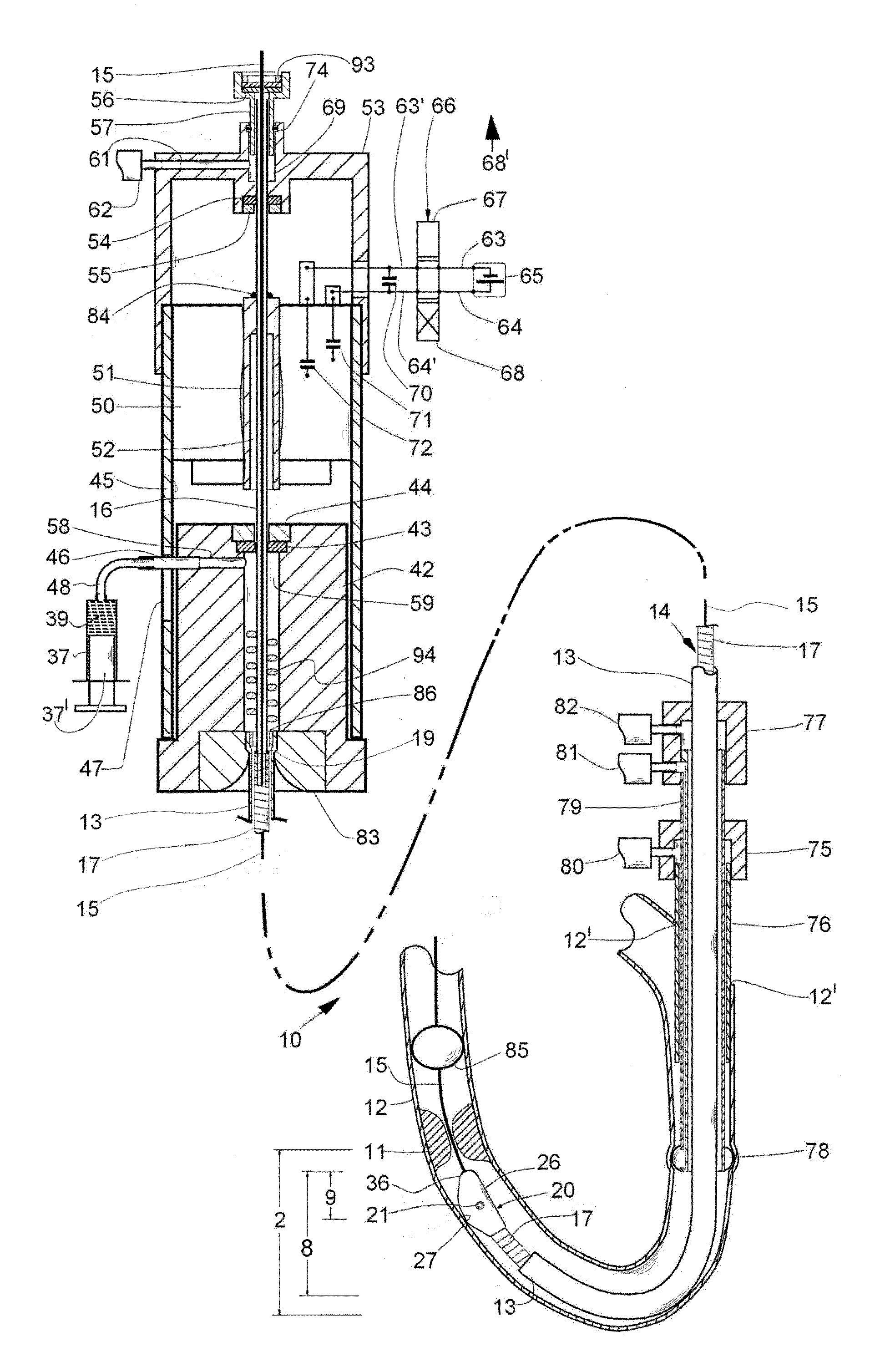
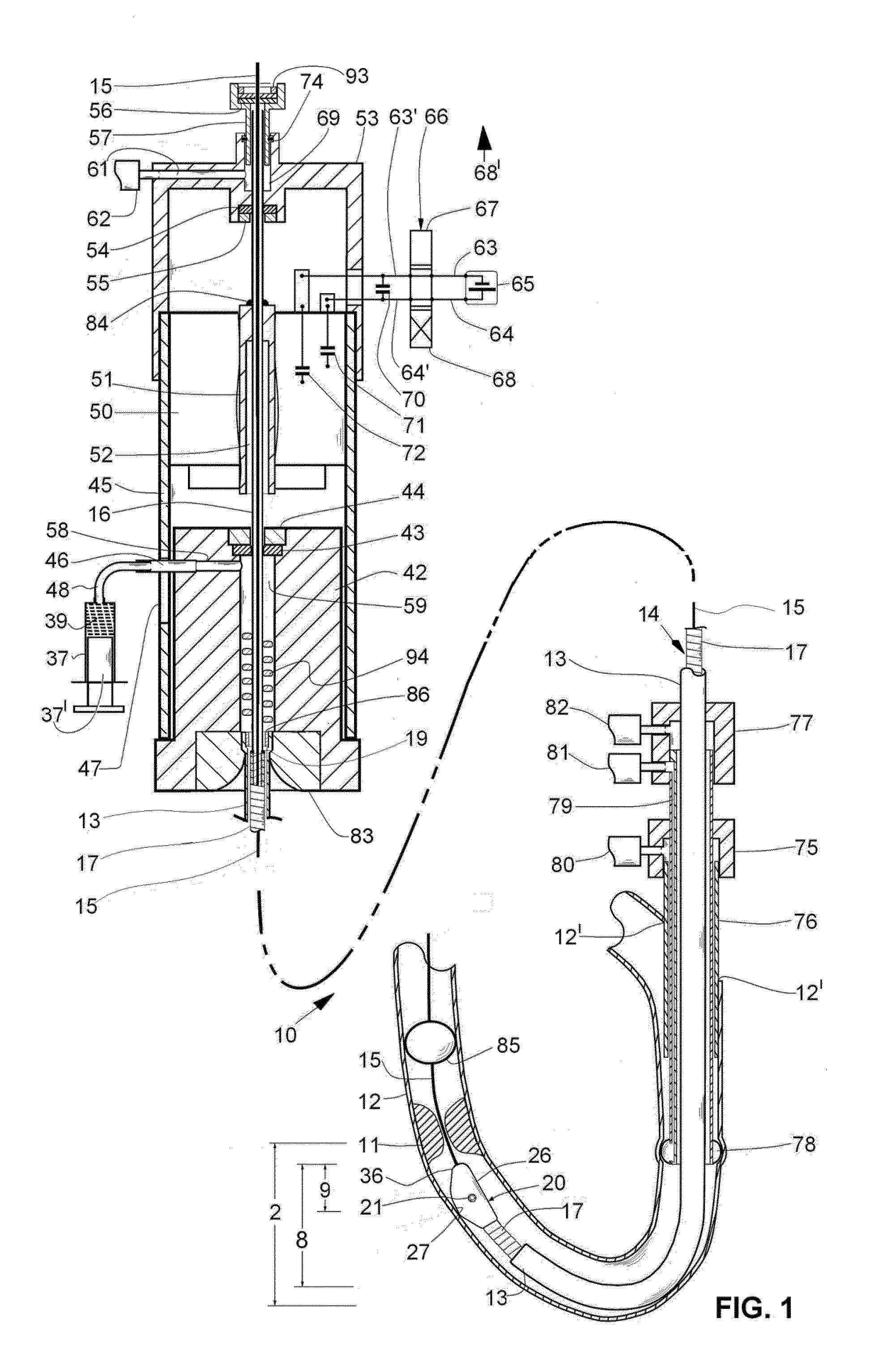
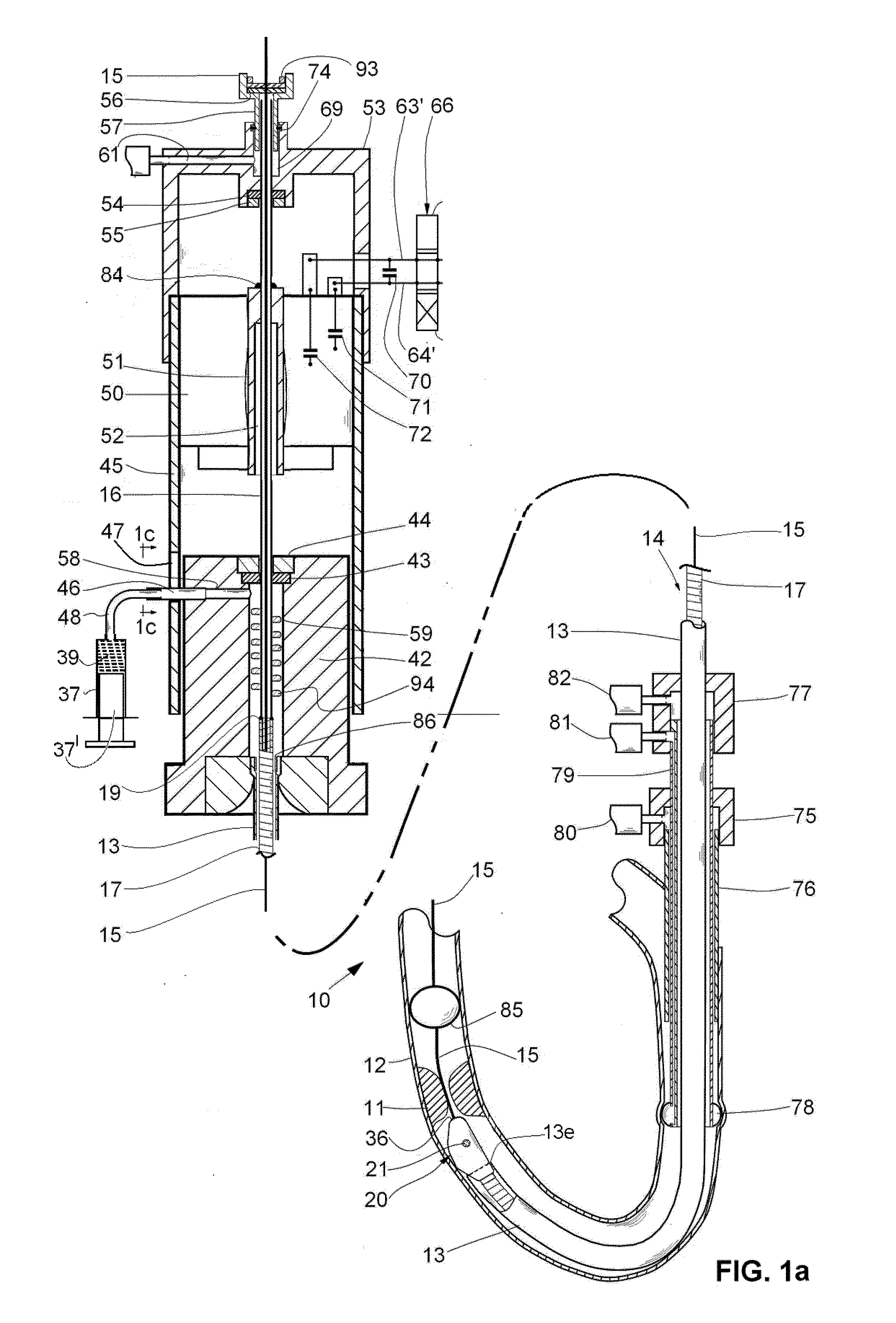
[0040]FIG. 1 shows a motorized rotary catheter 10, according to the present invention, for opening an obstruction 11 (e.g., blood clot; atheroma) in a bodily vessel 12 (e.g., a blood vessel).

[0041]The rotary catheter 10 comprises a motor-driven flexible hollow shaft 14, rotatably disposed in a flexible tube 13 that is preferably made of thin plastic material. A proximal portion 16 of the flexible hollow shaft is preferably a thin-walled tube and a distal portion of the flexible hollow shaft 17 is preferably made of a spiraled wire. The wire that is used to wind the spiraled wire preferably has a flattened cross-section (such a cross section can be obtained by taking a standard round wire and running it between rollers that squeeze and flatten it, please note FIGS. 4-6). The flexible hollow shaft portions 16 and 17 are preferably made of metal (e.g., stainless steel; Nitinol) and are connected together, for example, by a circumferential weld 19 (please note FIG. 1) or by two circumfe...


PUM

PropertyMeasurementUnit
flexibleaaaaaaaaaa
diameteraaaaaaaaaa
diametersaaaaaaaaaa

Abstract

A rotary catheter drive unit containing a motor and a seal-set, an output shaft of the motor being power transmittingly connected to a flexible shaft that is rotatably disposed through the seal-set, the seal-set comprising a bearing and an adjacent seal defining a first and a second concentric bores, respectively, the first bore being slightly larger than a diameter of the shaft so that it rotatably and accurately supports the shaft, the second bore being slightly smaller than the diameter so that it seals around the shaft, the bearing aligning the shaft, so that it is concentric with the second bore, by deflecting the shaft to compensate for eccentricity and misalignment of the second bore relative to the output shaft of the motor.

Description

CROSS REFERENCE TO RELATED APPLICATIONS[0001]Priority is claimed based on:[0002]U.S. patent application Ser. No. 13 / 695,232 by Shiber, entitled “ROTARY CATHETER FOR REMOVING OBSTRUCTIONS FROM BODILY VESSELS”, filed on Jan. 8, 2013, which claims priority from Pat. Appl. PCT / US2011 / 031197 filed on Apr. 5, 2011 by Shiber, and entitled “ROTARY CATHETER FOR REMOVING OBSTRUCTIONS FROM BODILY VESSELS”, which further claims priority from U.S. Provisional Pat. Appl. Ser. No. 61 / 343,796, filed on May 4, 2010 by Shiber and entitled “THROMBECTOMY AND ATHERECTOMY CATHETER” and U.S. Provisional Pat. Appl. 61 / 461,263 filed on Jan. 14, 2011 by Shiber and entitled “CATHETER FOR THROMBECTOMY AND ATHERECTOMY”; and[0003]U.S. patent application Ser. No. 14 / 238,983, filed on Feb. 14, 2014, by Shiber, entitled “ADAPTIVE ROTARY CATHETER FOR OPENING OBSTRUCTED BLOOD VESSELS”, which claims priority from Pat. Appl. PCT / US2012 / 050759 filed on Aug. 14, 2012 by Shiber, and entitled “ADAPTIVE ROTARY CATHETER FOR ...

Claims


Application Information

Patent Timeline
Patent Type & Authority Applications(United States)
IPC IPC(8): A61B17/3207A61B17/22
CPCA61B17/320758A61B17/22A61B2017/00336A61B2017/00398A61B2017/00526A61B2017/22039A61B2017/22048A61B2019/5466A61B2017/00734A61B2017/22038A61B2017/320044A61B2017/320766Y10T408/03B23B35/00B23B47/28
Inventor SHIBER, SAMUEL
Owner SHIBER SAMUEL
Learn More