Redundant Automation System

a technology of automation system and redundancy, applied in the field of redundancy automation system, can solve the problem that the communication performance cannot keep up, and achieve the effect of preventing temporal trailing and reducing the amount of management effor

Active Publication Date: 2015-04-02
SIEMENS AG
View PDF5 Cites 15 Cited by
  • Summary
  • Abstract
  • Description
  • Claims
  • Application Information

AI Technical Summary

Benefits of technology

[0014]One refinement of the invention provides for the respective master to be used to also transmit process input values to the slave at the time when the current releases are transmitted. The information relevant to the slave is combined or collected and is finally transmitted to the slave. In contrast with known temporal synchronization methods during which relevant information must be immediately transmitted to the slave, this means a considerably reduced amount of “management effort” both for the automa

Problems solved by technology

This is because the communication performance usually ca

Method used


Image

  • Redundant Automation System
  • Redundant Automation System
  • Redundant Automation System

Examples


Embodiment Construction

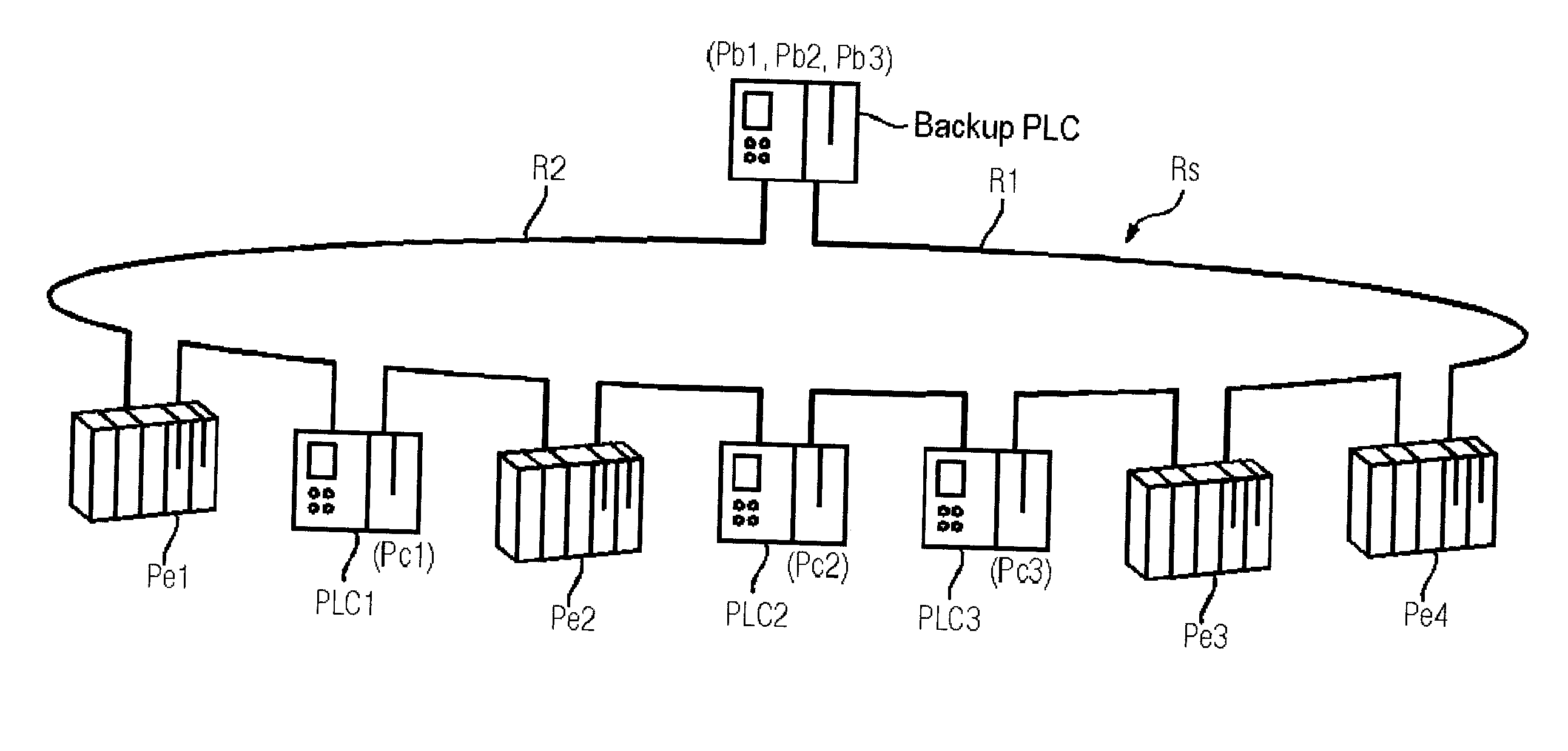
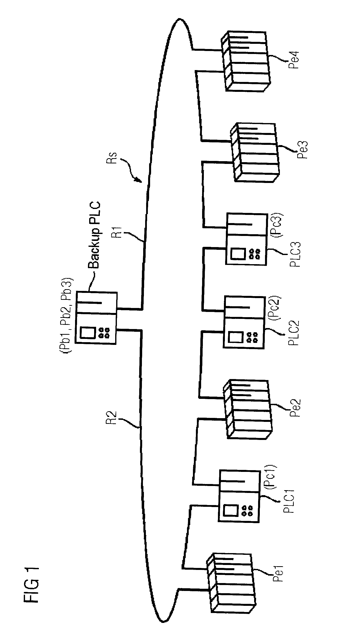
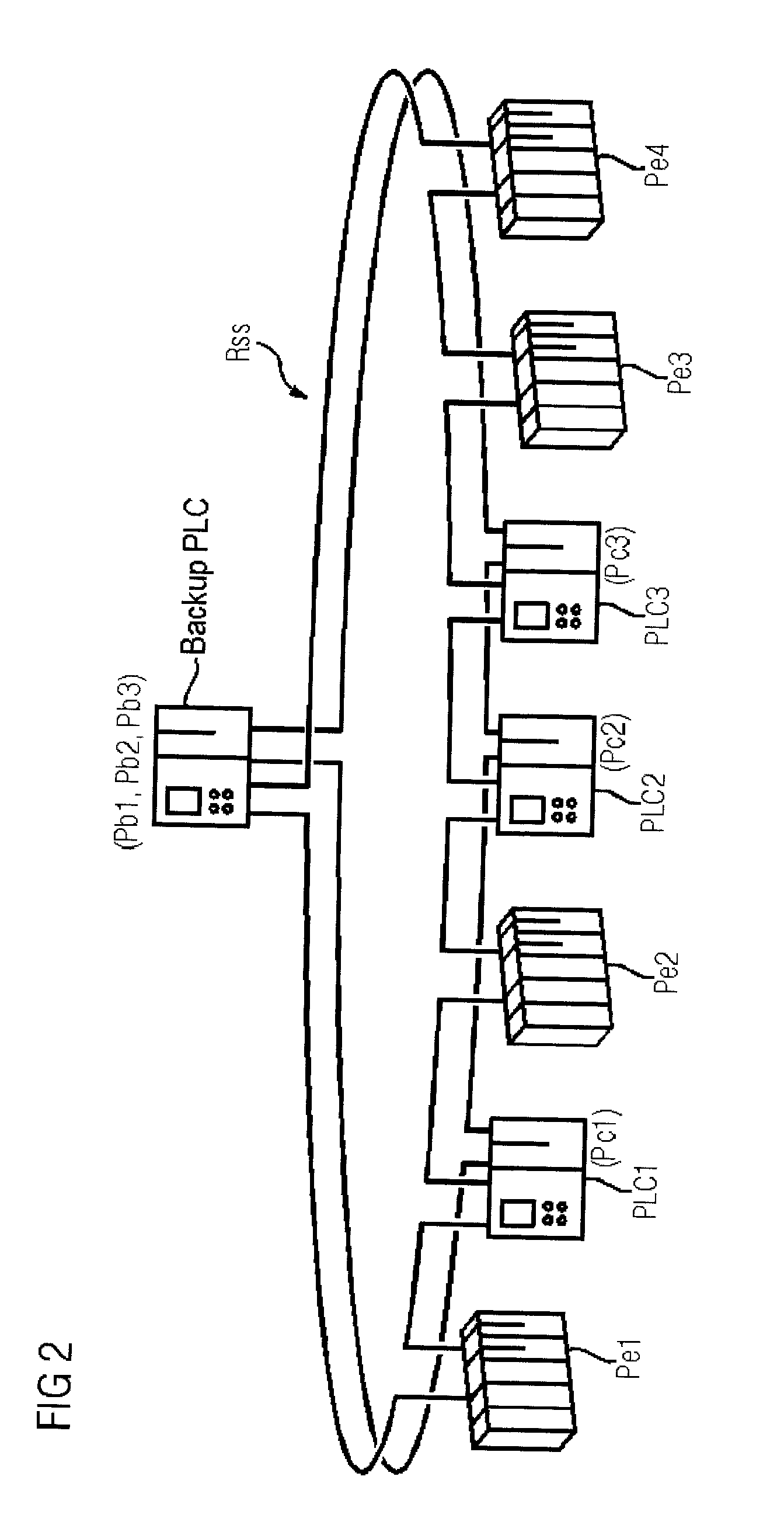
[0021]Reference is made to FIG. 6 which illustrates a redundant automation system that is known in the art and comprises two subsystems. A first subsystem Ta is in the form of a master automation device (master PLC) and a second subsystem Tb is in the form of a slave automation device (backup PLC), and the two subsystems are connected to a peripheral unit Pe via a field bus Fb. In this case, the field bus Fb complies with the PROFIBUS-DP specification, for example. In principle, other bus systems, for example Ethernet, Fieldbus, Modbus, or else parallel bus systems, are also suitable. The peripheral unit Pe receives, via input lines Es, signals from transducers or measuring transducers, which are used to detect a process state, outputs via output lines As, and signals to actuators, which are used to influence the process. The process as well as the transducers, measuring transducers and actuators are not illustrated in FIG. 6 for the sake of clarity. The two subsystems Ta, Tb of the...


PUM


Abstract

A redundant automation system having a plurality of automation devices which are connected to one another comprises a plurality of master devices and a slave device. Each of the plurality of automation devices processes a control program in order to control a technical process. At least one of the plurality of automation devices operates as a slave and at least two of the plurality of automation devices, each operates as a master. The plurality of master devices is each configured to run a respective master program and to process processing sections of the respective master program of the respective master program, and the slave device is configured to process a corresponding slave control program for each master control program run by the plurality of master devices and, if one of the plurality of master devices fails, to assume the function of the failed master.

Description

FIELD OF INVENTION[0001]The invention relates to a redundant automation system having a plurality of automation devices that are connected to one another, wherein each of the plurality of automation devices processes a control program in order to control a technical process.DESCRIPTION OF THE RELATED ART[0002]In the automation environment, there is an increasing demand for highly available solutions (e.g., H systems) which are suitable for minimizing possible downtimes of the installation. The development of such highly available solutions is very cost-intensive with an H system usually used in the automation environment being distinguished by the fact that two or more subsystems in the form of automation devices or computer systems are coupled to one another via a synchronization connection. In principle, both subsystems can have read and / or write access to the peripheral units connected to this H system. One of the two subsystems leads with respect to the peripherals connected to ...

Claims


Application Information

Patent Timeline
IPC IPC(8): G06F11/20
CPCG06F11/2023G06F11/2097G05B9/03G05B19/058G05B2219/14129G05B2219/14131
Inventor GROSCH, THOMASLAFORSCH, JURGENRENSCHLER, ALBERT
Owner SIEMENS AG
Why Eureka
Try Eureka