Compression Wire Joints

a compression joint and wire connection technology, applied in the direction of connecting contact member materials, manufacturing tools, mechanical equipment, etc., can solve the problems of large installation error potential, increased use of aluminum cables, and high copper cost, and achieve the effect of tight connection and reduced error potential

Active Publication Date: 2015-04-09
THOMAS & BETTS INT INC
View PDF7 Cites 9 Cited by
  • Summary
  • Abstract
  • Description
  • Claims
  • Application Information

AI Technical Summary

Benefits of technology

[0005]The presently disclosed compression wire joint provides a tighter connection between various wire sizes and types, yet allows standard crimping dies to be used. Because it can accommodate multiple sizes of wires, and is designed to be used with a standard crimping die, the potential for error is greatly reduced.

Problems solved by technology

However, due to increases in the cost of copper, the use of aluminum cable has increased.
Without a connector designed for joining aluminum and copper, the connection may loosen over time and result in overheating.
As a result, an installer must carry a large supply of the various sizes of crimping dies that are specific to each application, and there exists a large potential for installation errors if the incorrect wire, connector, or die is used.
With high voltage applications, errors by installers and loose connections can lead to failure of the connection, resulting in overheating or even fires.

Method used


Image

  • Compression Wire Joints
  • Compression Wire Joints
  • Compression Wire Joints

Examples


Embodiment Construction

[0019]The following detailed description is presented to enable any person skilled in the art to make and use the invention. For purposes of explanation, specific details are set forth to provide a thorough understanding of the present invention. However, it will be apparent to one skilled in the art that these specific details are not required to practice the invention. Descriptions of specific applications are provided only as representative examples. Various modifications to the preferred embodiments will be readily apparent to one skilled in the art, and the general principles defined herein may be applied to other embodiments and applications without departing from the scope of the invention. The present invention is not intended to be limited to the embodiments shown, but is to be accorded the widest possible scope consistent with the principles and features disclosed herein.

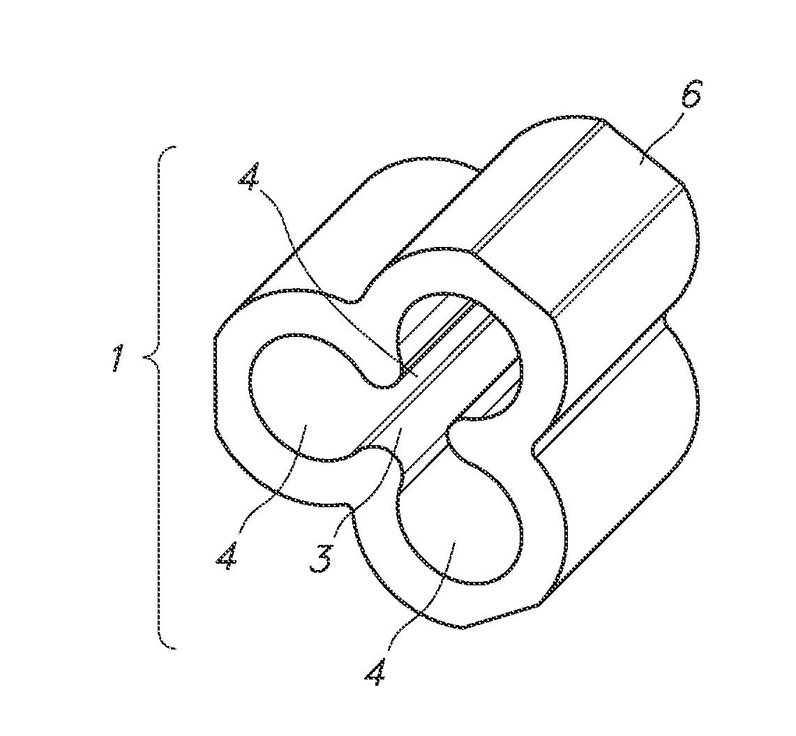
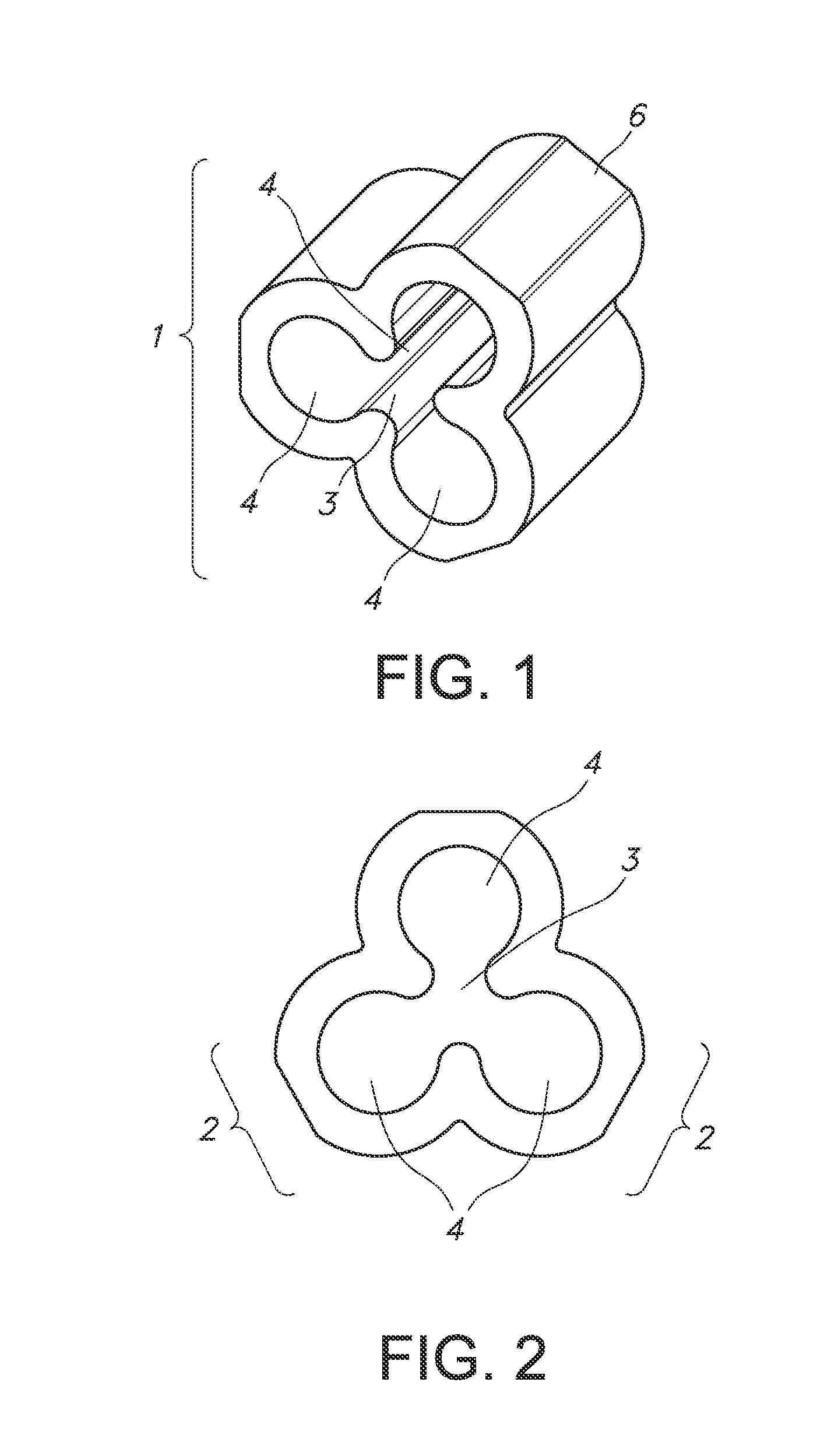
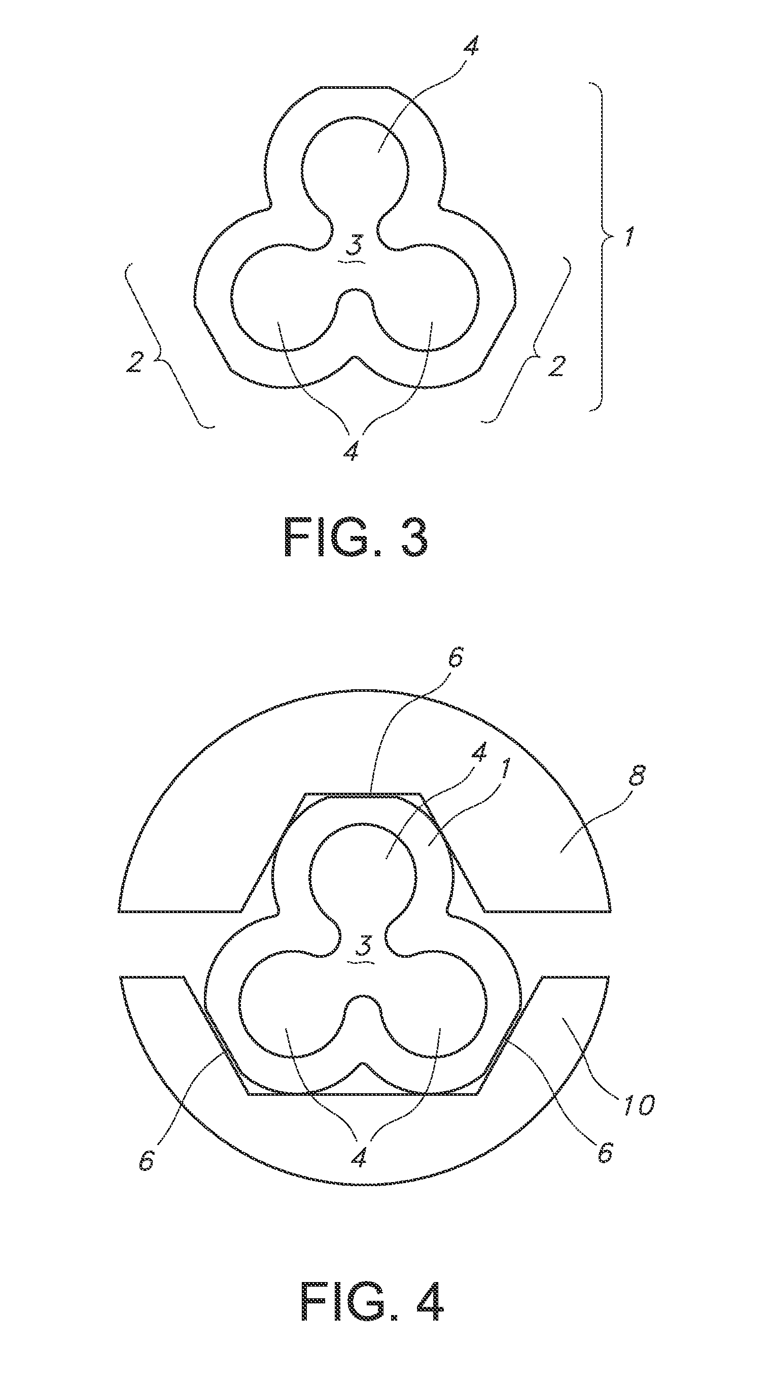
[0020]Referring to the drawings, FIGS. 1 and 2 illustrate an embodiment of the compression wire joint 1...


PUM

PropertyMeasurementUnit
lengthsaaaaaaaaaa
lengthaaaaaaaaaa
lengthsaaaaaaaaaa

Abstract

An improved compression wire joint is disclosed that allows for tighter connections between the wires. It is particularly useful for connecting copper and aluminum wires together because it provides a tight connection that better accommodates thermal expansion of each wire.

Description

CROSS-REFERENCES TO RELATED APPLICATIONS[0001]This application claims benefit of priority to U.S. Provisional Application Ser. No. 61 / 887,122, filed Oct. 4, 2013, which is hereby incorporated by reference herein in its entirety.FIELD OF THE INVENTION[0002]The present invention is generally directed toward a new compression joint used to connect wires.BACKGROUND OF THE INVENTION[0003]Wire joints are often used to connect multiple copper conductors using a tubular connector. The wires are placed in the tubular connector and crimped together. However, due to increases in the cost of copper, the use of aluminum cable has increased. Joining copper and aluminum requires a special connector compatible with aluminum because aluminum wiring has a thermal expansion rate that is different from that of copper. Without a connector designed for joining aluminum and copper, the connection may loosen over time and result in overheating.[0004]The typical connector used to join conductors of copper a...

Claims


Application Information

Patent Timeline
Patent Type & Authority Applications(United States)
IPC IPC(8): F16G11/02
CPCF16G11/02H01R4/183H01R4/62H01R2101/00Y10T29/53657
Inventor CAWOOD, MATTHEW D.VALLETTE, RONALD
Owner THOMAS & BETTS INT INC
Why Eureka
Try Eureka