
Wireless handheld controller

Inactive Publication Date: 2015-04-09
BEKLEMISEV JURIJ
View PDF0 Cites 1 Cited by
  • Summary
  • Abstract
  • Description
  • Claims
  • Application Information

AI Technical Summary

Benefits of technology

[0019]Many of the issues mentioned above are solved by a hand-held portable wireless battery powered remote control device as described herein. The user interface of the device is designed to achieve the goal of allowing quick access to large number for controllable parameters. The choice of elements of the device is influenced by better tactile feeling and the device may be operated with w

Problems solved by technology

However such devices often fail when used in harsh environments of extreme temperature, mechanical shock, dirt and moisture.
In addition, many of these touch screen based user interfaces lack input speed regarding receipt of user input commands via the touch screen.
However consumer type equipment chosen to perform professional highly specialized tasks include a number of drawbacks such as: lack of rigid mechanical design to withstand kicks and drops; failure of touch screens to operate reliably when in contact with moisture of any kind, such as sweat, skin oil, rain drops, etc.
; regular erroneous input of information; slower input of information compared to computer keyboards or other user input device; lack of a field swappable battery; and lack of a replacement aerial option for stronger wireless communication link.
The chances are relatively high of the touch tablet getting accidentally damaged by kicking or dropping from considerable heights in harsh environments, such as sites where live concerts are set up, du

Method used


Image

  • Wireless handheld controller
  • Wireless handheld controller
  • Wireless handheld controller

Examples


Example

DETAILED DESCRIPTION OF THE DRAWINGS AND THE PRESENTLY PREFERRED EMBODIMENTS

[0029]Embodiments of a wireless handheld controller can be used for, but are not limited to mixing sound. Although use of the wireless handheld controller is described in some instances in the context of audio sound mixing and control, other applications, such as lighting control are also contemplated. Accordingly, the wireless handheld controller is not limited to use in only audio sound mixing / control applications.

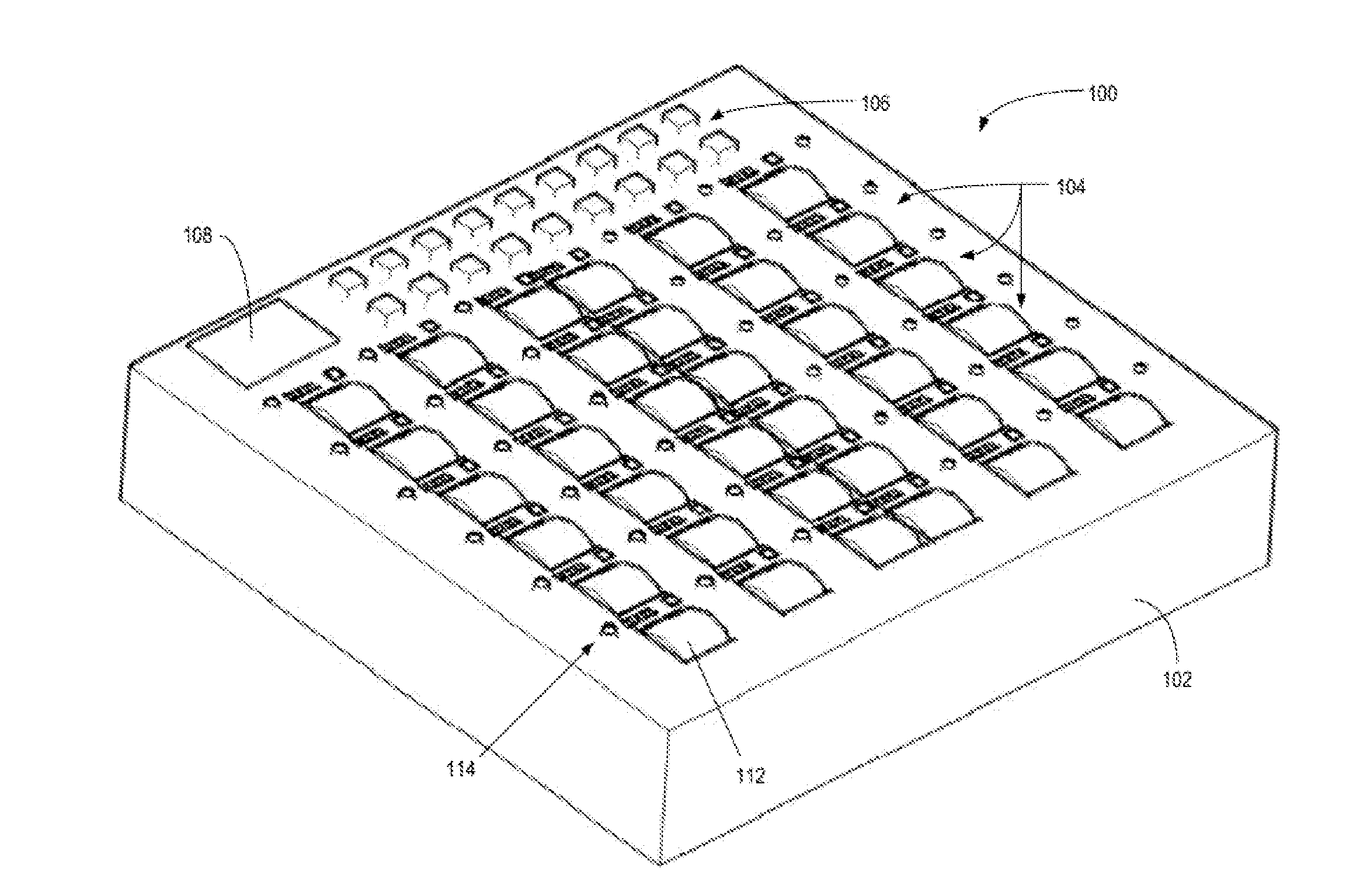
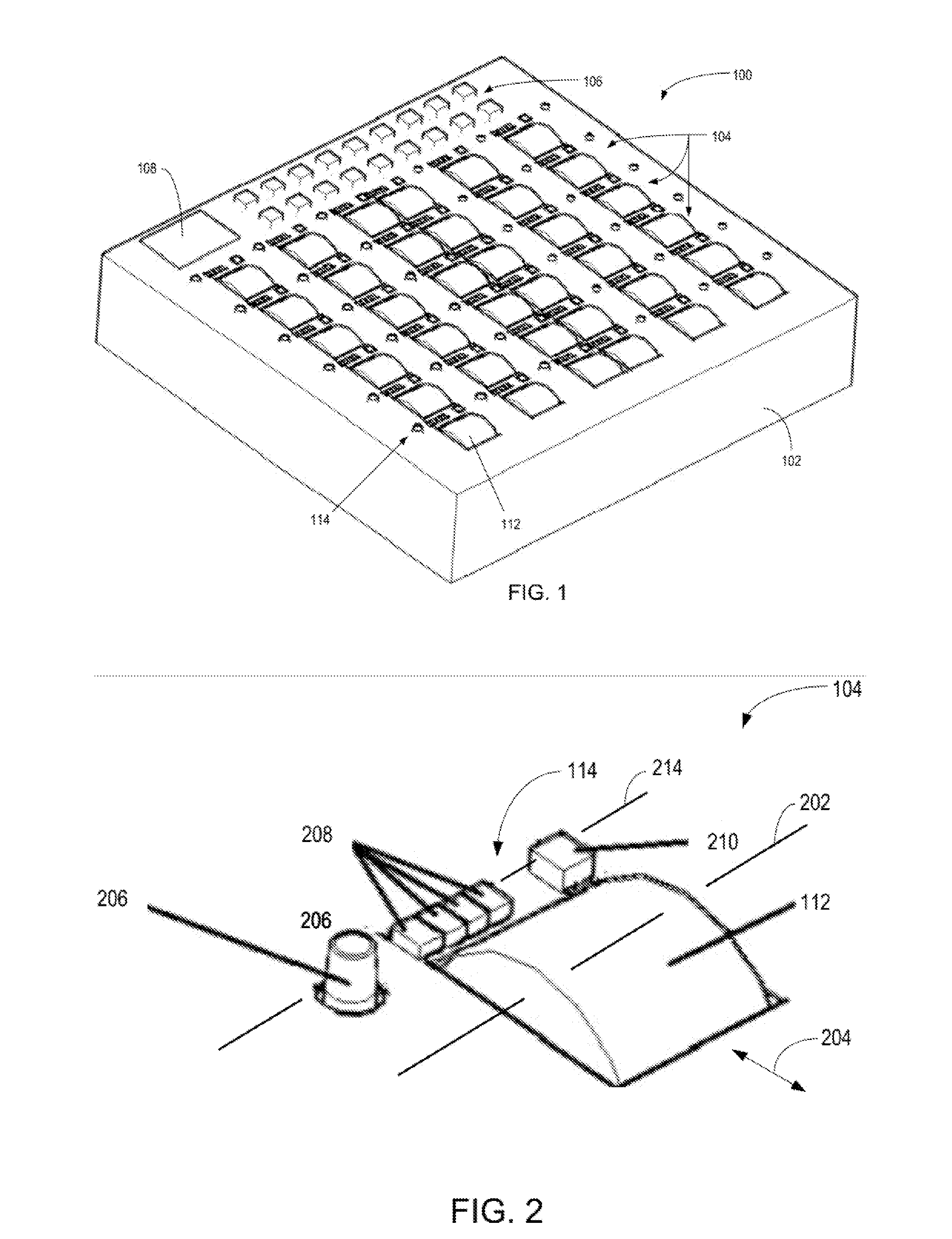
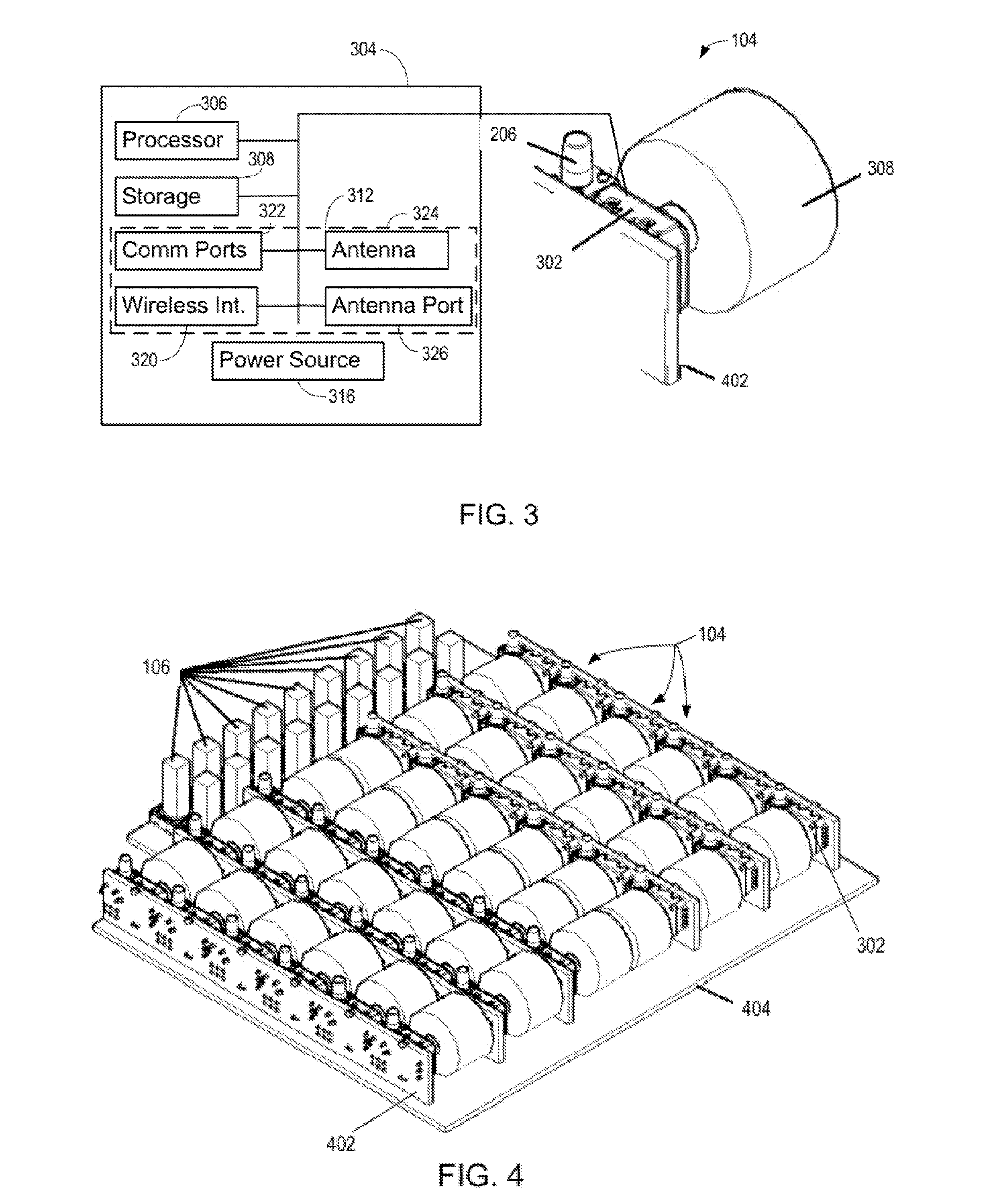
[0030]FIG. 1 is a perspective view of an example embodiment of a wireless handheld controller 100. The wireless handheld controller 100 can include a housing 102 and a user interface. The user interface can include scroll wheel assemblies 104, function keys 106, and a display 108. In the illustrated embodiment, there are thirty-six scroll wheel assemblies 104 disposed in openings in the housing 102 in a group to form a 6×6 matrix, which may be referred to as a parameter section of the user interf...


PUM


Abstract

A wireless handheld controller includes a housing and a plurality of scroll wheel assemblies mounted in the housing. Each of the scroll wheel assemblies including a rotatable member and a key adjacently associated with respective rotatable members. The wireless handheld controller also includes circuitry in electrical communication with the scroll wheel assemblies. The circuitry is configured to control the device and provide remote control of equipment in communication with the device. The circuitry comprising a movement sensing system configured to sense movement of the rotatable member, and a key sensing system configured to sense a mode signal received from the key. The circuitry configured to operate in a first mode initiated with the mode signal in which each one of the plurality of scroll wheel assemblies are representative of one of a plurality of input channels, and a second mode initiated with the mode signal in which each one of the plurality of scroll wheel assemblies are representative of parameters of only one of the plurality of input channels.

Description

RELATED APPLICATIONS[0001]The present patent document claims the benefit of the filing date under 35 U.S.C. §119 of U.S. Provisional Patent Application Ser. No. 61 / 887,454, filed Oct. 7, 2013, which is hereby incorporated by reference.BACKGROUND[0002]1. Technical Field[0003]The present invention relates in general to remote control of equipment and more particularly to control surfaces for sound, lighting, video and such equipment.1. BACKGROUND INFORMATION[0004]Devices can be controlled remotely using a control board, or a computer, or a control board that includes a computer. Control boards typically include indicators of conditions of the devices and variable switches and / or knobs to control the remote device(s). A computer may generate a graphical user interface that can be used to control the remote device(s).BRIEF SUMMARY[0005]Engineers can use consumer type touch tablet computer devices to adjust an audio sound mix or program intelligent lighting in indoor as well as outdoor v...

Claims


Application Information

Patent Timeline
IPC IPC(8): G06F3/0362
CPCG06F3/0362H04H60/04
Inventor BEKLEMISEV, JURIJ
Owner BEKLEMISEV JURIJ
Learn More