Stabilized Device For Moving A Plurality Of Containers

a technology of stabilizing device and container, which is applied in the direction of de-stacking articles, packaging, thin material processing, etc., can solve the problems of affecting the stability of the container, the tipped container, the pallet may fall off, etc., and achieves the effect of reducing down time and operating costs, preventing damage to the container, and being easy to manufacture and assembl

Active Publication Date: 2010-07-22
ARROWHEAD SYST
View PDF41 Cites 4 Cited by
  • Summary
  • Abstract
  • Description
  • Claims
  • Application Information

AI Technical Summary

Benefits of technology

[0007]By way of summary, the present invention is directed to a palletizer or depalletizer that includes a pin matrix. A primary object of the invention is to provide a palletizer or depalletizer that can move containers, e.g., bottles, relative to a pallet while maintaining the containers upright and preventing damage to the containers. Another object of the present invention is to provide a palletizer or depalletizer that may be used with containers having a variety of shapes and sizes, so that the palletizer or depalletizer does not have to be recalibrated for each different configuration of container. A further object of the invention is to provide a palletizer or depalletizer wherein the pin matrix may be selectively used depending on the type of container to be moved. Another object of the invention is to provide an apparatus that is ruggedized and reliable, thereby decreasing down time and operating costs. Another object of the invention is to provide an apparatus that has one or more of the characteristics discussed above but which is relatively simple to manufacture and assemble using a minimum of equipment.

Problems solved by technology

However, these types of systems can have undesirable consequences.
For example, some of the containers may be tipped over during the process, particularly if the containers are top heavy or unstable, e.g., containers that are reverse tapered and thus have a higher center of gravity or a relatively small foot area compared to the upper portions of the container.
Additionally, some containers, e.g., those near the edges of the group, may shift position and fall off of the pallet or the conveyor belt during movement.
Still further, the conventional manner of moving containers onto or off pallets will likely cause individual containers to knock into one another, which may damage and / or destroy the containers.

Method used


Image

  • Stabilized Device For Moving A Plurality Of Containers
  • Stabilized Device For Moving A Plurality Of Containers
  • Stabilized Device For Moving A Plurality Of Containers

Examples


Embodiment Construction

[0039]The present invention and the various features and advantageous details thereof are explained more fully with reference to the non-limiting embodiments described in detail in the following description.

1. System Overture

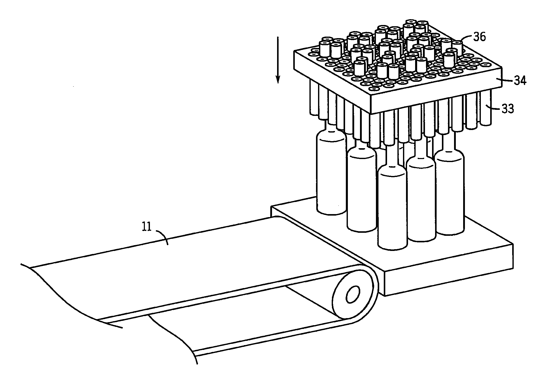
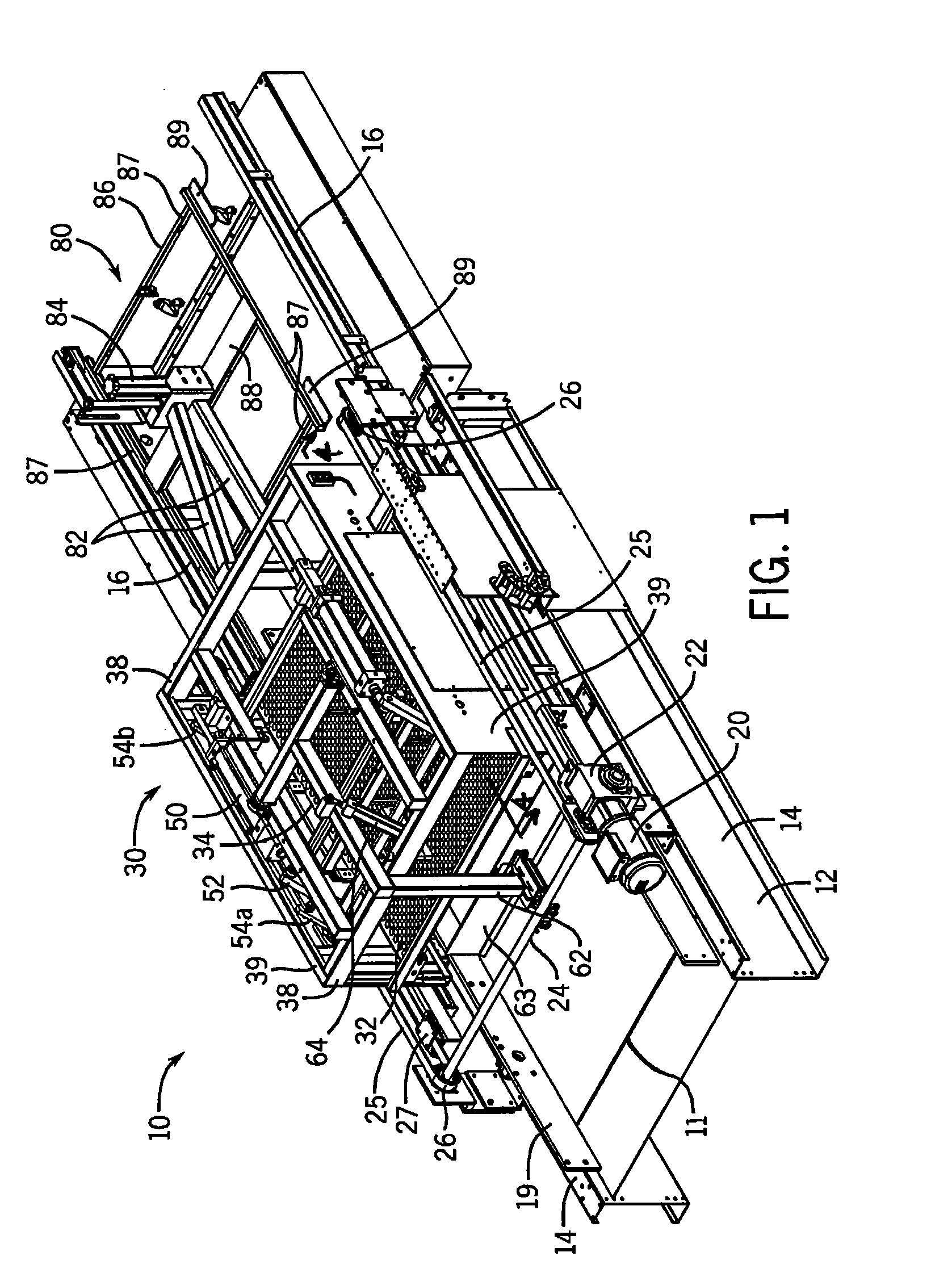
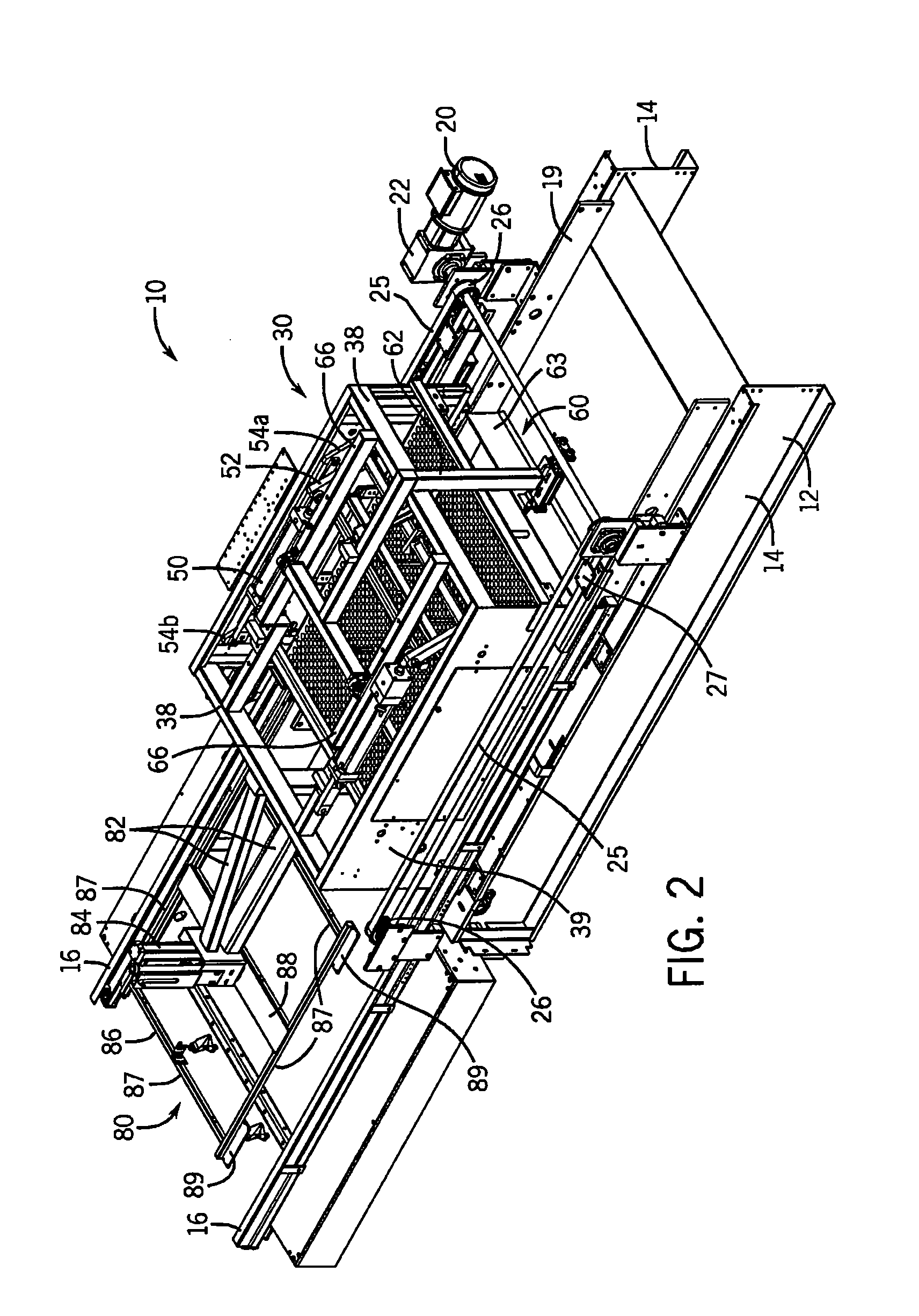
[0040]Generally speaking, the present invention relates to a device for moving a plurality of containers while maintaining the containers in an upright orientation. The device may be used in a palletizing application for moving containers onto a pallet, or in a depalletizing application for moving containers off a pallet. The drawings and the following description illustrate the device of the present invention used in a depalletizing application for moving products off a pallet and onto a conveyor belt. It is understood, however, that the device of the present invention may also be used in a palletizing application to move or sweep the containers onto a pallet. It is also understood that the device of the present invention is not necessarily limited to moving co...


PUM


Abstract

A device for moving containers or other objects relative to a surface such as a pallet includes a frame and a pin matrix movably attached to the frame. The pin matrix includes an array of pins and is housed in a plate having apertures for receiving the pins. The device further includes a pair of tracks that movably support the pin matrix. A method for moving containers or other objects relative to a surface includes the steps of moving the pin matrix over the objects, lowering the pin matrix, securing the objects within the pin matrix, moving the pin matrix and the objects relative to the surface, and raising the pin matrix.

Description

BACKGROUND OF THE INVENTION[0001]1. Field of the Invention[0002]The present invention relates in general to the field of palletizers and depalletizers. More particularly, the present invention relates to a palletizer or depalletizer for moving containers of various shapes, e.g., bottles, to or from a pallet.[0003]2. Discussion of the Related Art[0004]Containers, e.g., bottles, are typically shipped and stored using pallets. At some point, the containers must be moved onto or removed from the pallet. In order to do so, the pallet is typically positioned near the end of a conveyor belt. In a depalletizing application, the containers are pushed off of the pallet and onto the conveyor belt as a group. In a palletizing application, the containers are pushed onto the pallet from the conveyor belt.[0005]However, these types of systems can have undesirable consequences. For example, some of the containers may be tipped over during the process, particularly if the containers are top heavy or...

Claims


Application Information

Patent Timeline
Patent Type & Authority Applications(United States)
IPC IPC(8): B65G47/74B65G57/00B65G59/00
CPCB65G47/82B65G2201/0244B65G59/005Y10S414/108Y10S414/13
Inventor STRINGFIELD, MARVIN LLINDAUER, CARY A.
Owner ARROWHEAD SYST
Why Eureka
Try Eureka