Vacuum pre-conditioner with automatic drainage device

A vacuum resurfacing and automatic drainage technology, which is applied in the preparation of tobacco, application, tobacco, etc., can solve the problems of increasing evacuation load and high energy consumption, and achieve the effect of reducing evacuation load, reducing condensed water, and simple process

Pending Publication Date: 2018-12-07
郑州市碧亮真空设备有限公司
View PDF0 Cites 1 Cited by
  • Summary
  • Abstract
  • Description
  • Claims
  • Application Information

AI Technical Summary

Problems solved by technology

[0007] The purpose of the present invention is to provide a vacuum dampening machine with an automatic drainage device to solve the problems of increasing the pu

Method used


Image

  • Vacuum pre-conditioner with automatic drainage device
  • Vacuum pre-conditioner with automatic drainage device
  • Vacuum pre-conditioner with automatic drainage device

Examples


Embodiment 1

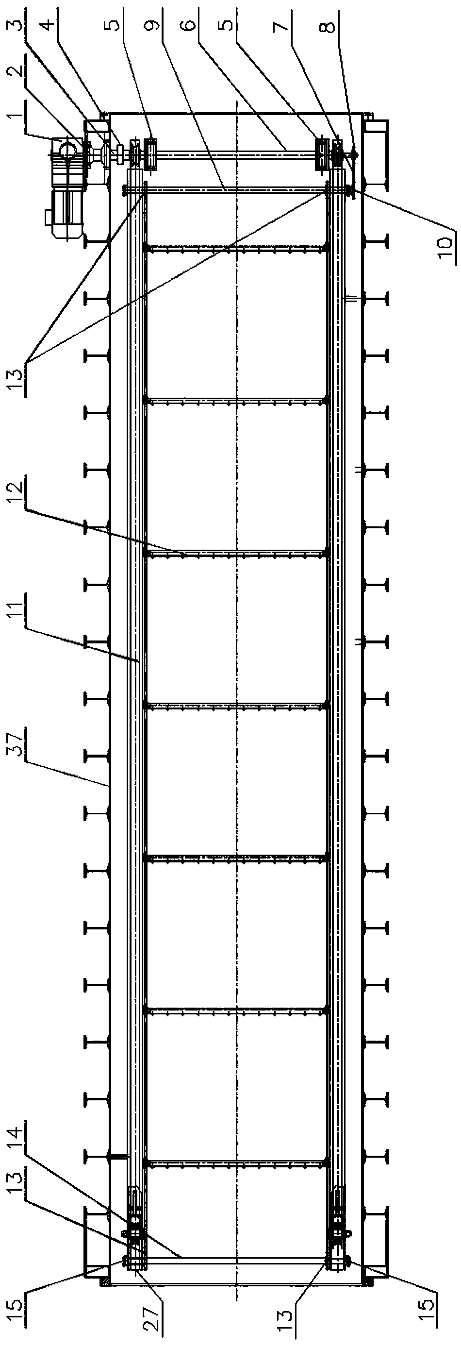
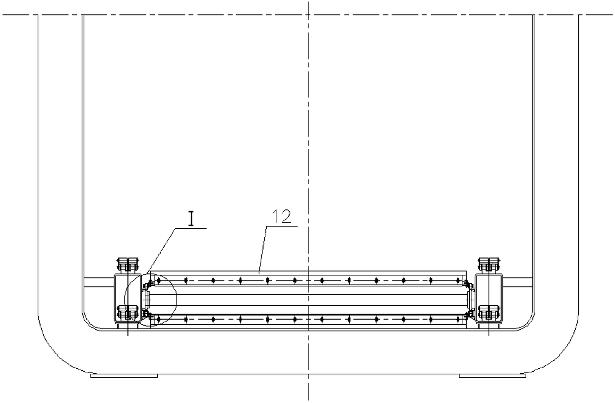
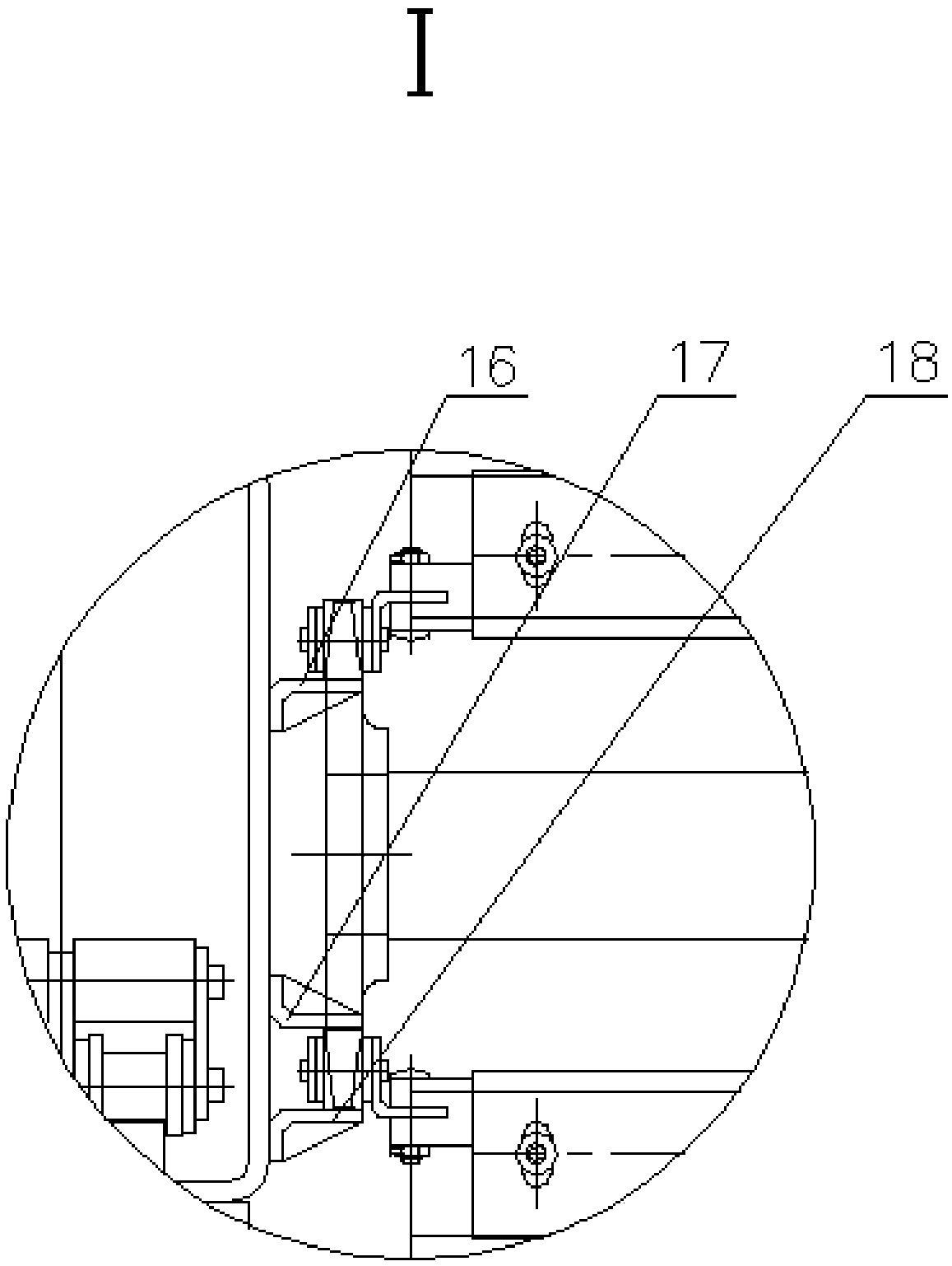
[0048] Embodiment one: see Figure 1-Figure 5 As shown, a vacuum dampening machine with an automatic drainage device includes a dampening machine casing 37, and the bottom of the dampening machine casing 37 is provided with an automatic drainage device. The bottom of the dampening machine casing 37 is rectangular. A scraper assembly for wiping water at the bottom of the cabinet and a power mechanism that drives the scraper assembly to move back and forth at the bottom of the humidifier cabinet.

[0049] The power mechanism includes a driving shaft 9 and a driven shaft 14 respectively arranged at both ends of the humidifier casing 37, the driving shaft 9 is connected to a rotating drive device, and both ends of the driving shaft 9 and the driven shaft 14 are connected to scrapers Sprocket 13, the scraper sprocket 13 at both ends of the driving shaft 9 is connected to the scraper sprocket 13 at both ends of the driven shaft 14 through two scraper chains 11, each A scraper assem...

Embodiment 2

[0054] Embodiment two: if Figure 6 As shown, the rotary driving device includes a scraper chain drive motor 23, a power shaft 25, a drive sprocket 10 connected to the end of the drive shaft 9 and a drive chain 7, and the scraper chain drive motor 23 is arranged in the wet Outside the cabinet 37, the power shaft 25 passes through the outer wall of the humidifier cabinet 37, and one end of the power shaft 25 outside the humidifier cabinet 37 is connected with the scraper chain drive motor 23, and the power shaft 25 is in the One end in the humidifier casing 37 is connected with the power sprocket 2 26, and the transmission sprocket 10 and the power sprocket 2 26 are connected through the transmission chain 1 7. When the scraper chain drive motor 23 is turned on, the scraper assembly 12 will follow the The scraper chain translates and rotates to realize the function of wiping water on the bottom of the humidifier cabinet 37, thereby pushing the condensed water at the bottom of t...

Embodiment 3

[0059] Embodiment three: see Figure 11-Figure 16 , a vacuum conditioner with automatic drainage device, comprising a conditioner casing 37, the bottom of the conditioner casing 37 is provided with an automatic drainage device, and the automatic drainage device includes a scraper assembly for scraping water at the bottom of the conditioner casing 37 And the power mechanism that drives the scraper assembly to move back and forth at the bottom of the humidifier casing 37 .

[0060] The power mechanism includes a sliding shaft 40, a lead screw 46, a lead screw nut 47, a lead screw driving device and a scraper drag shaft 52, and one lead screw 46 is respectively arranged at the front and rear sections of the bottom of the humidifier box. , the screw driving device is arranged at the bottom of the humidifier box, the screw driving device drives the screw to rotate, the screw nut 47 is screwed on the screw 46, and the scraper drags The shaft 52 is fixedly connected to the lead scre...


PUM


Abstract

The invention relates to conditioning equipment. A vacuum pre-conditioner with an automatic drainage device comprises a pre-conditioner box body, wherein the inner wall of the pre-conditioner box bodyis coated with a waterproof and heat-retaining coating, the bottom of the pre-conditioner box body is provided with the automatic drainage device, and the automatic drainage device comprises a scraper blade assembly used for wiping water at the bottom of the pre-conditioner box body and a power mechanism used for driving the scraper blade assembly to move back and forth at the bottom of the pre-conditioner box body. The vacuum pre-conditioner with the automatic drainage device has the advantages that accumulated water and sundries at the bottom of the box body are cleaned away, condensed water is wiped out of the box body, the pumping load and pumping time of a next conditioning process are saved, steam consumption during humidification is also reduced, the effect of steam on the temperature rise of the wall of the box body when humidification is performed on a heat-retaining material applied on the inner wall of the box body is greatly reduced, and the steam consumption is also reduced.

Description

technical field [0001] The invention relates to a dampening device, in particular to a vacuum dampening machine with an automatic drainage device. Background technique [0002] Vacuum moisture resurfacing machine is the first process equipment in cigarette processing. Materials (such as tobacco leaves) that have been stored for a long time must be vacuum rehydrated before processing. Its purpose is: 1) Properly increase the moisture content and temperature of tobacco leaves to make tobacco leaves Become soft and increase toughness to meet the needs of subsequent operations; 2) insecticide and sterilization, when the humidification temperature is greater than 70 ° C, adults such as tobacco powder borers in the tobacco leaves can be killed, so that the treated tobacco leaves can Safe storage; 3) Remove green miscellaneous gas of raw materials In high temperature and high humidity environment, the chemical composition in tobacco leaves will change, the green miscellaneous smell...

Claims


Application Information

Patent Timeline
IPC IPC(8): A24B3/04
CPCA24B3/04
Inventor 石峰曹延召石峥
Owner 郑州市碧亮真空设备有限公司
Why Eureka
Try Eureka