Automated ball mounting process and system with solder ball testing

Active Publication Date: 2005-12-22
INTEGRATED DEVICE TECH INC
View PDF16 Cites 3 Cited by
  • Summary
  • Abstract
  • Description
  • Claims
  • Application Information

AI Technical Summary

Benefits of technology

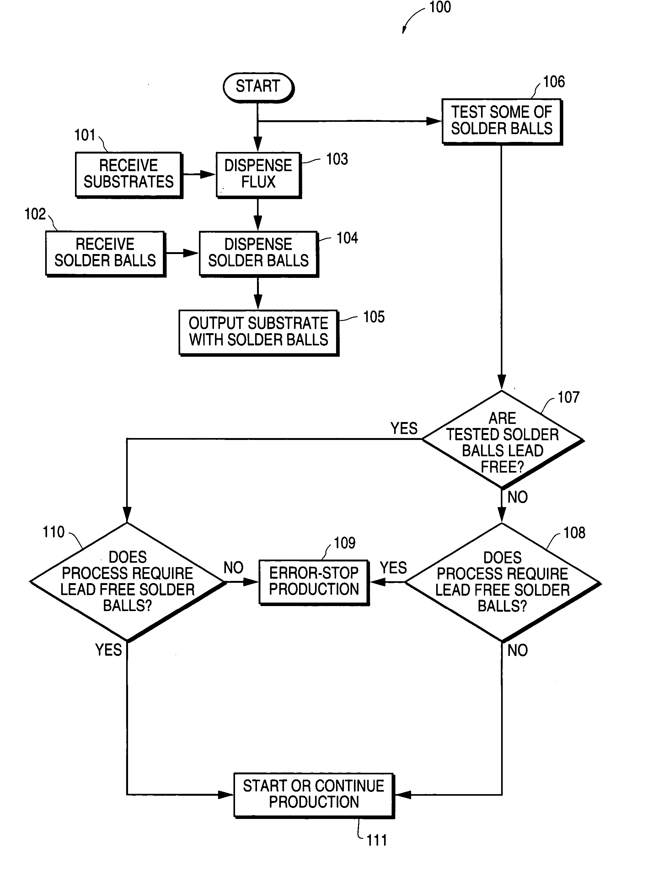
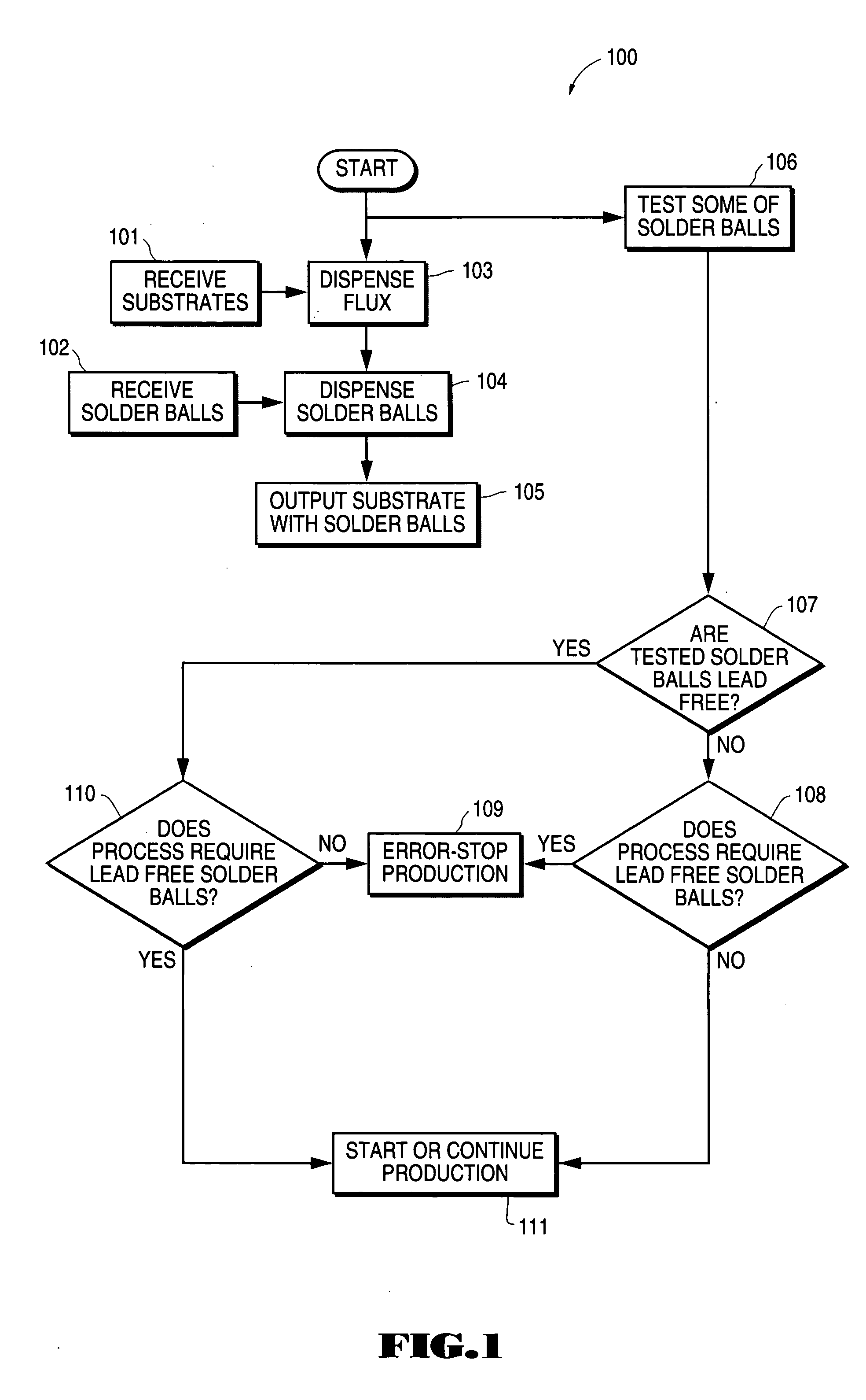
[0006] The present invention provides an automated solder ball mounting process and system in which solder ball type is tested in order to assure that the correct type of solder ball is being used. This results in reduced down time and reduced defect rates.
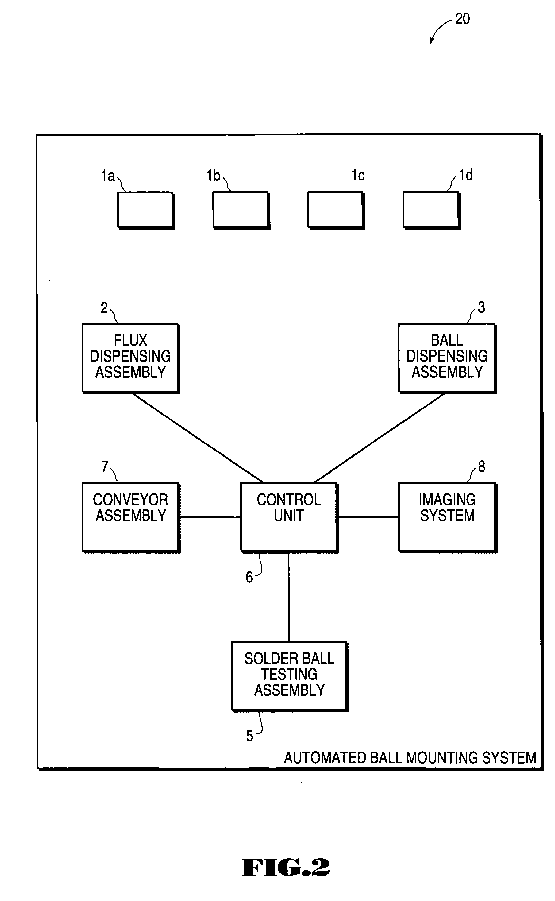
[0007] An automated solder ball mounting process and an automated ball mounting system are disclosed in which solder balls are tested to determine solder ball type. When the test is performed and the wrong solder ball type is being used an error message is indicated and the solder ball mounting process is stopped. This prevents product defects that can result from the use of the wrong solder ball type. In addition, a single solder ball mounting system can be used to attach both s

Problems solved by technology

However, when both standard solder balls and lead free solder balls are used in the same manufacturing facility, workers can accidentally input the wrong type of solder ball into a solder ball mounting system.
This can result in numerous defective products being fabricated before the problem is discovered.
The lab test delays the start-up o

Method used


Image

  • Automated ball mounting process and system with solder ball testing
  • Automated ball mounting process and system with solder ball testing
  • Automated ball mounting process and system with solder ball testing

Examples


Example

[0017] The drawings referred to In this description should be understood as not being drawn to scale.

DETAILED DESCRIPTION OF THE INVENTION

[0018] Reference will now be made in detail to the preferred embodiments of the invention, examples of which are illustrated in the accompanying drawings. While the invention will be described in conjunction with the preferred embodiments, it will be understood that they are not intended to limit the invention to these embodiments. On the contrary, the invention is intended to cover alternatives, modifications and equivalents, which may be included within the spirit and scope of the invention as defined by the appended claims. Furthermore, in the following detailed description of the present invention, numerous specific details are set forth in order to provide a thorough understanding of the present invention. However, it will be obvious to one of ordinary skill in the art that the present invention may be practiced without these specific detai...


PUM

PropertyMeasurementUnit
Angleaaaaaaaaaa
Angleaaaaaaaaaa
Angleaaaaaaaaaa

Abstract

An automated ball mounting process and system are disclosed In which solder balls are tested by heating the solder balls to a temperature between the eutectic temperature of lead-tin and the melting temperature of a lead free solder ball. If the heated solder balls melt they are standard solder balls. If they do not melt they are lead free solder balls. Solder balls that are input into the automated ball mounting process are automatically tested to determine solder ball type. When the test indicates that the wrong type of solder ball is being used an error message is indicated and the solder ball mounting process stops.

Description

FIELD OF THE INVENTION [0001] The present invention relates to the field of semiconductor devices. More specifically, the present invention relates to solder ball mounting processes and systems. BACKGROUND ART [0002] Automated solder ball mounting systems have been developed that quickly and accurately attach solder balls to substrates. The solder ball type most commonly used in these systems is the standard solder ball. Standard solder balls are formed of a lead-tin alloy. However, for environmental reasons there has been an increasing need for the use of lead free solder balls. [0003] The requirement that a manufacturing facility be able to attach both standard solder balls and lead free solder balls has forced some manufacturing facilities to purchase additional dedicated ball mounting systems to mount lead free solder balls. However, when both standard solder balls and lead free solder balls are used in the same manufacturing facility, workers can accidentally input the wrong ty...

Claims


Application Information

Patent Timeline
IPC IPC(8): B23K3/06B23K31/00H05K3/34
CPCH05K3/3478B23K3/0623
Inventor SONG, KONG LAMCHOE, PENG CHEONGMEDINA, TIC
Owner INTEGRATED DEVICE TECH INC
Why Eureka
Try Eureka