Base frame

a base frame and frame technology, applied in the field of base frames, can solve the problems of increasing increasing cost or cost, and reducing the strength of the structure, so as to achieve the effect of reducing the cost of analytical cost and die-manufacturing cost and allowing for the expansion of the spa

Inactive Publication Date: 2015-04-09
INVENTEC PUDONG TECH CORPOARTION +1
View PDF1 Cites 2 Cited by
  • Summary
  • Abstract
  • Description
  • Claims
  • Application Information

AI Technical Summary

Benefits of technology

The present invention is providing a base frame with reinforcing ribs that strengthen its structure. These ribs extend towards the edges of the base frame, making the surface flat. Additionally, each rib has a V-shaped profile, which provides space to the base frame without compromising its strength. Overall, the base frame has greater strength and supporting force.

Problems solved by technology

However, while a workpiece is formed at the sheet metal or bonded to the sheet metal by riveting process, the sheet metal is vulnerable to downforce due to the workpiece or force due to riveting process.
Sagging or deformation of the sheet metal results in inconvenience while operators of production line want to assemble other parts at the sheet metal.
For example, if computer cases are deformed or sag, components such as printed circuit boards cannot be securely installed at the cases so that components such as printed circuit boards may be damaged by deformed computer cases.
However, the foregoing solutions cause either cost increase or analytical cost and die-manufacturing cost.

Method used


Image

  • Base frame
  • Base frame
  • Base frame

Examples


Embodiment Construction

[0021]Reference will now be made in detail to the present embodiments of the invention, examples of which are illustrated in the accompanying drawings. Wherever possible, the same reference numbers are used in the drawings and the description to refer to the same or like parts.

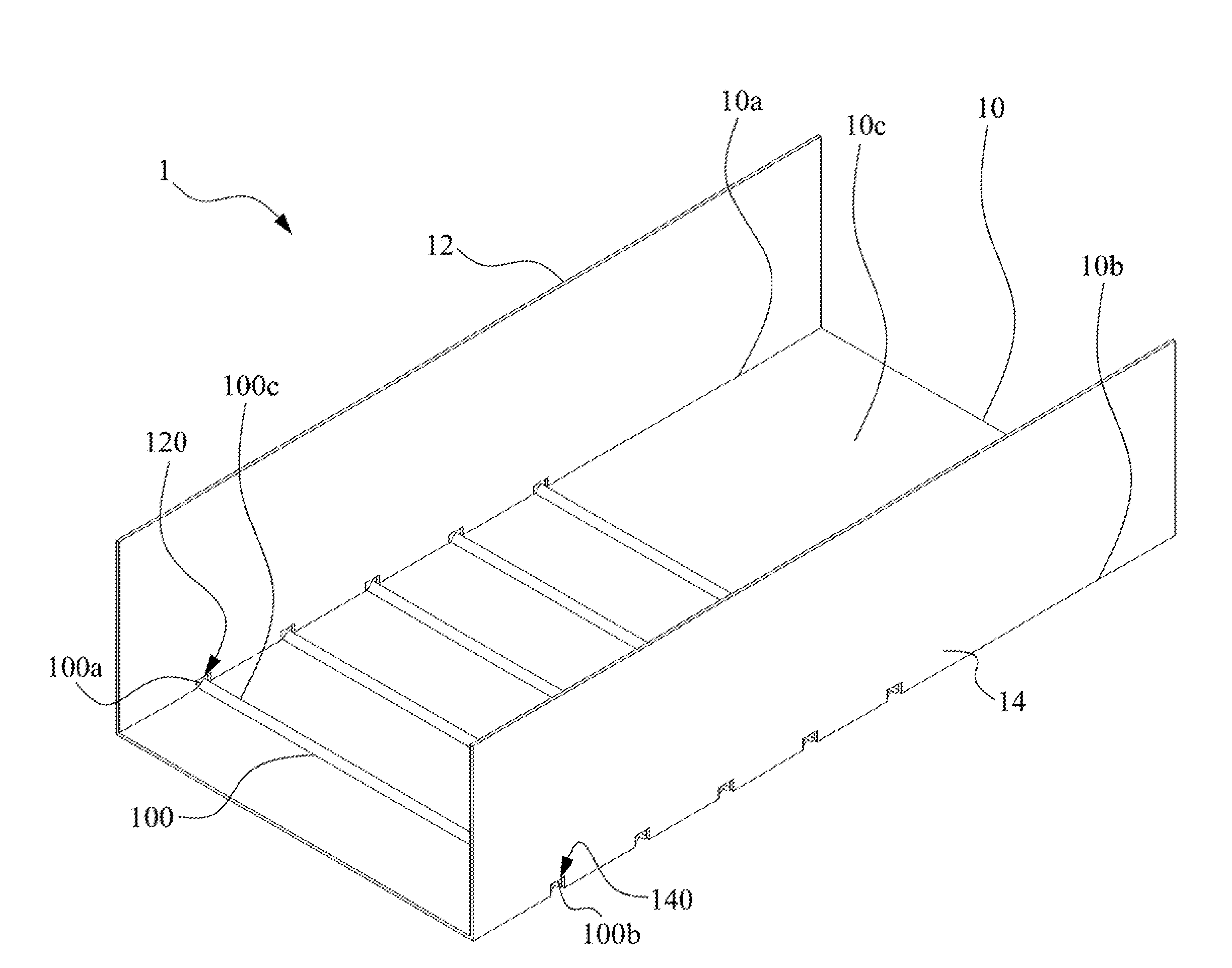
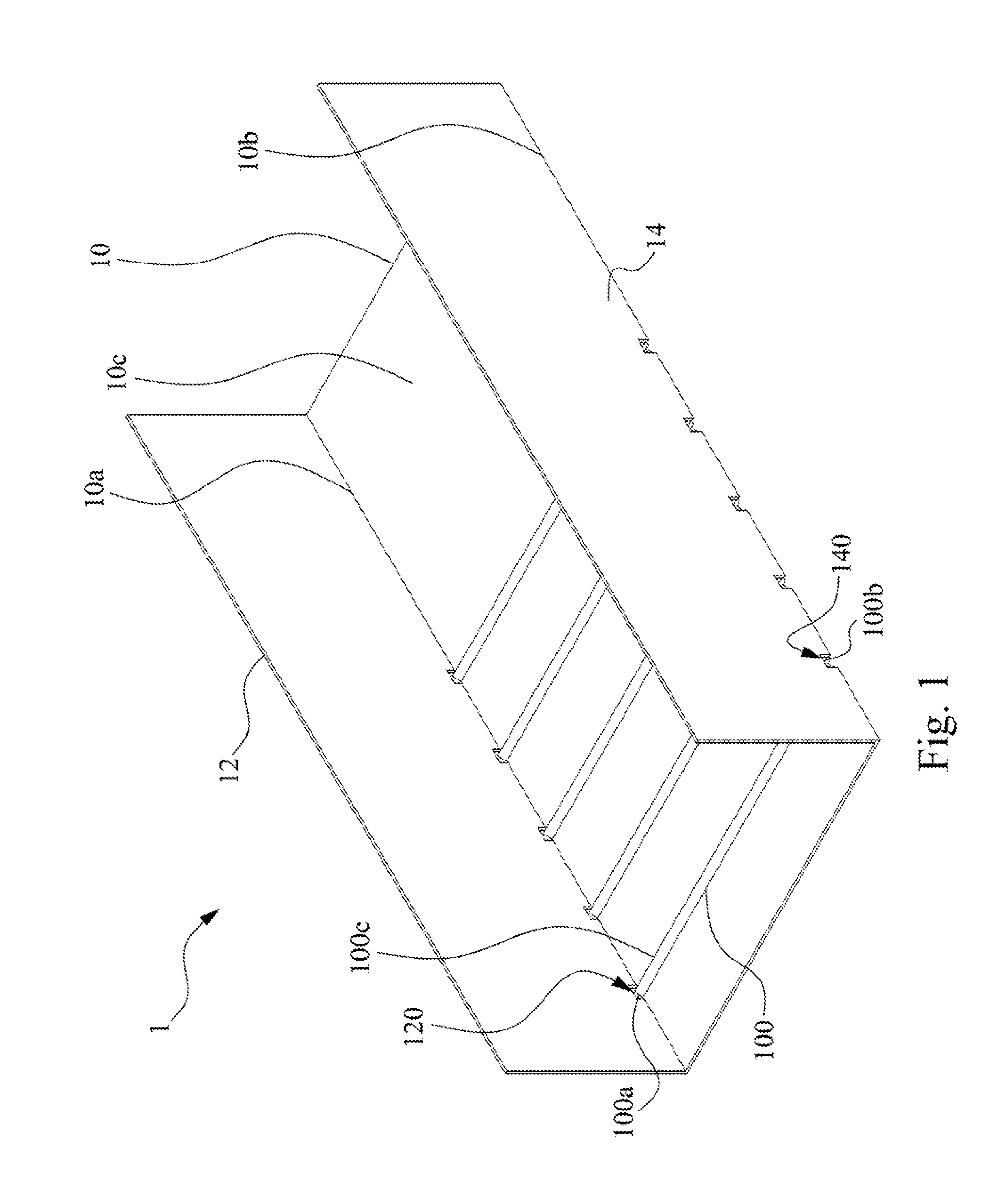
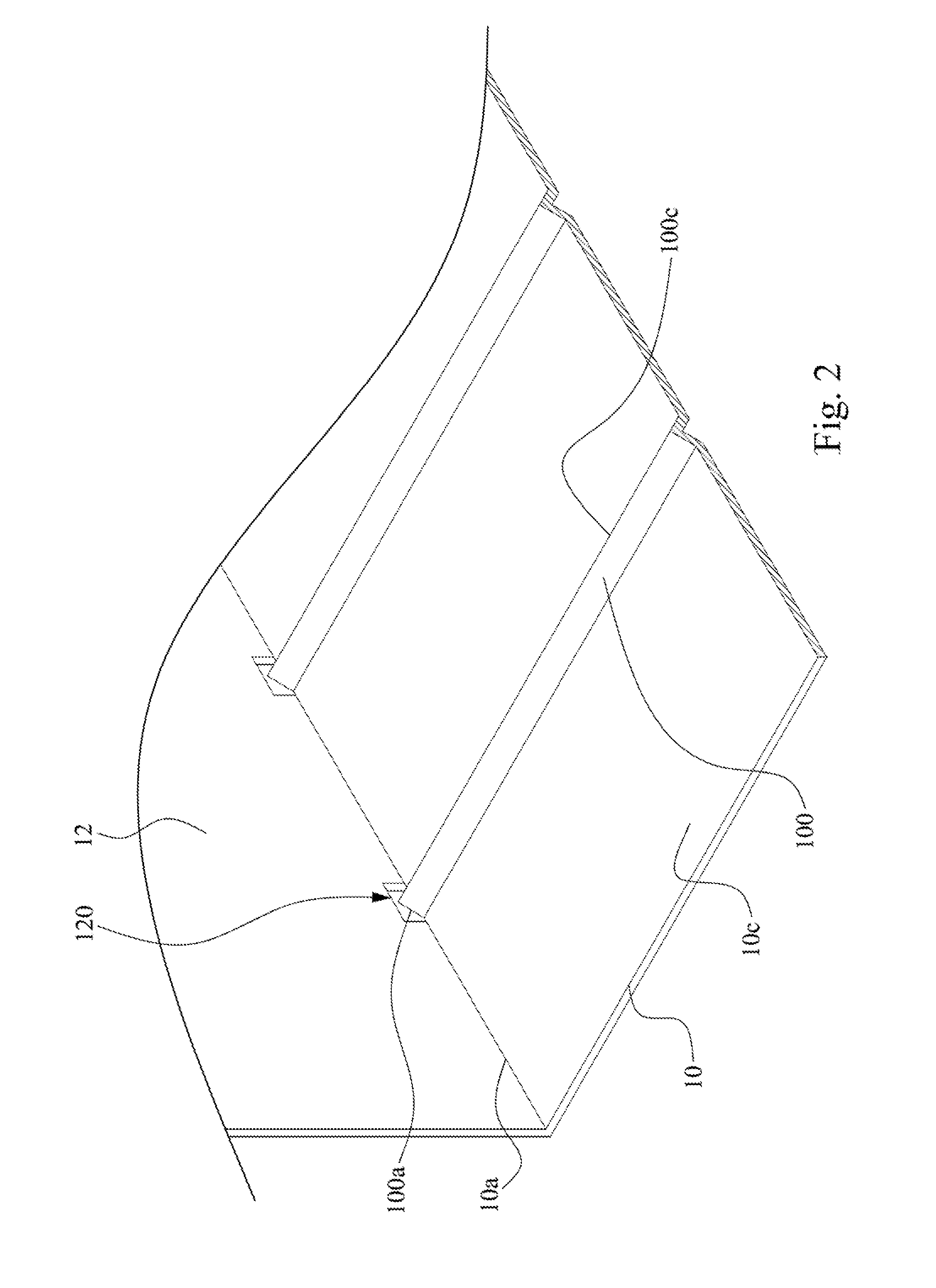
[0022]FIG. 1 illustrates a perspective view of a base frame 1 according to one embodiment of the present invention. FIG. 2 illustrates a partial perspective view with an edge removed of the base frame 1 of FIG. 1.

[0023]As shown in FIGS. 1 and 2, according to the embodiment, the base frame 1 may be part of server case (not shown) for supporting components (not shown) within the server case. For example, 2.5-inch Small Form Factor (SSF) storage device or 3.5-inch. Large Form Factor (LFF) storage device. However, the present invention is not limited to these applications. The base frame 1 of the present invention may be implemented within the server (e.g. blade series servers) to supports internal components.

[002...


PUM

PropertyMeasurementUnit
Widthaaaaaaaaaa
Distanceaaaaaaaaaa

Abstract

A base frame includes a base plate, a first side plate, and a second side plate. The base plate has a first edge and a second edge. The base plate includes a plurality of V-shaped reinforcing ribs. Each V-shaped reinforcing rib has a first end and a second end. The first and second ends are located at the first and second edges, respectively. The first side plate is connected to the first edge and has a plurality of first through holes. Each first through hole is locationally configured next to the first edge and faces to the corresponding first end. The second side plate is connected to the second edge and has a plurality of second through holes. Each second through hole is locationally configured next to the second edge and faces to the corresponding second end.

Description

RELATED APPLICATIONS[0001]This application claims priority to Chinese Application Serial Number 201310467131.6, filed Oct. 9, 2013, which is herein incorporated by reference.BACKGROUND[0002]1. Technical Field[0003]The present invention relates to a base frame. More particularly, the present invention relates to a base frame which is made from metal plate and subjected to metal bending process.[0004]2. Description of Related Art[0005]While sheet metal is subjected to metalworking, reinforcing ribs and supplemental ribs are formed at the sheet metal to enhance strength of material. However, while a workpiece is formed at the sheet metal or bonded to the sheet metal by riveting process, the sheet metal is vulnerable to downforce due to the workpiece or force due to riveting process. Thus, the sheet metal will sag and be deformed toward a specific direction. Sagging or deformation of the sheet metal results in inconvenience while operators of production line want to assemble other parts...

Claims


Application Information

Patent Timeline
IPC IPC(8): B32B15/01
CPCB32B15/01G06F1/186Y10T428/12361
Inventor YANG, CHUN-YINGHSIAO, CHI-CHENGPENG, YING-CHAO
Owner INVENTEC PUDONG TECH CORPOARTION
Why Eureka
Try Eureka