Method and apparatus for wireless device performance testing

a wireless device and performance testing technology, applied in the field of electromagnetic communication, can solve the problems of increasing the size and complexity of the test setup, increasing the cost of the test unit, and increasing the complexity of the test system,

Active Publication Date: 2015-04-09
GOOGLE TECH HLDG LLC
View PDF3 Cites 13 Cited by
  • Summary
  • Abstract
  • Description
  • Claims
  • Application Information

AI Technical Summary

Problems solved by technology

The increased size and complexity of the test setups can cost substantially more per unit test to run than earlier test systems.
All of these constraints result in a relatively large radius of the sphere at which the probe antennas are mounted.
In comparison, when many fixed probe antennas are used, either a larger number of dedicated complex amplifiers are needed and / or high quality radio frequency switches are used, which costs substantially.
Also, the distance of the probe antennas from the wireless unit must be larger to prevent antenna coupling, which also increases costs.

Method used


Image

  • Method and apparatus for wireless device performance testing
  • Method and apparatus for wireless device performance testing
  • Method and apparatus for wireless device performance testing

Examples


Embodiment Construction

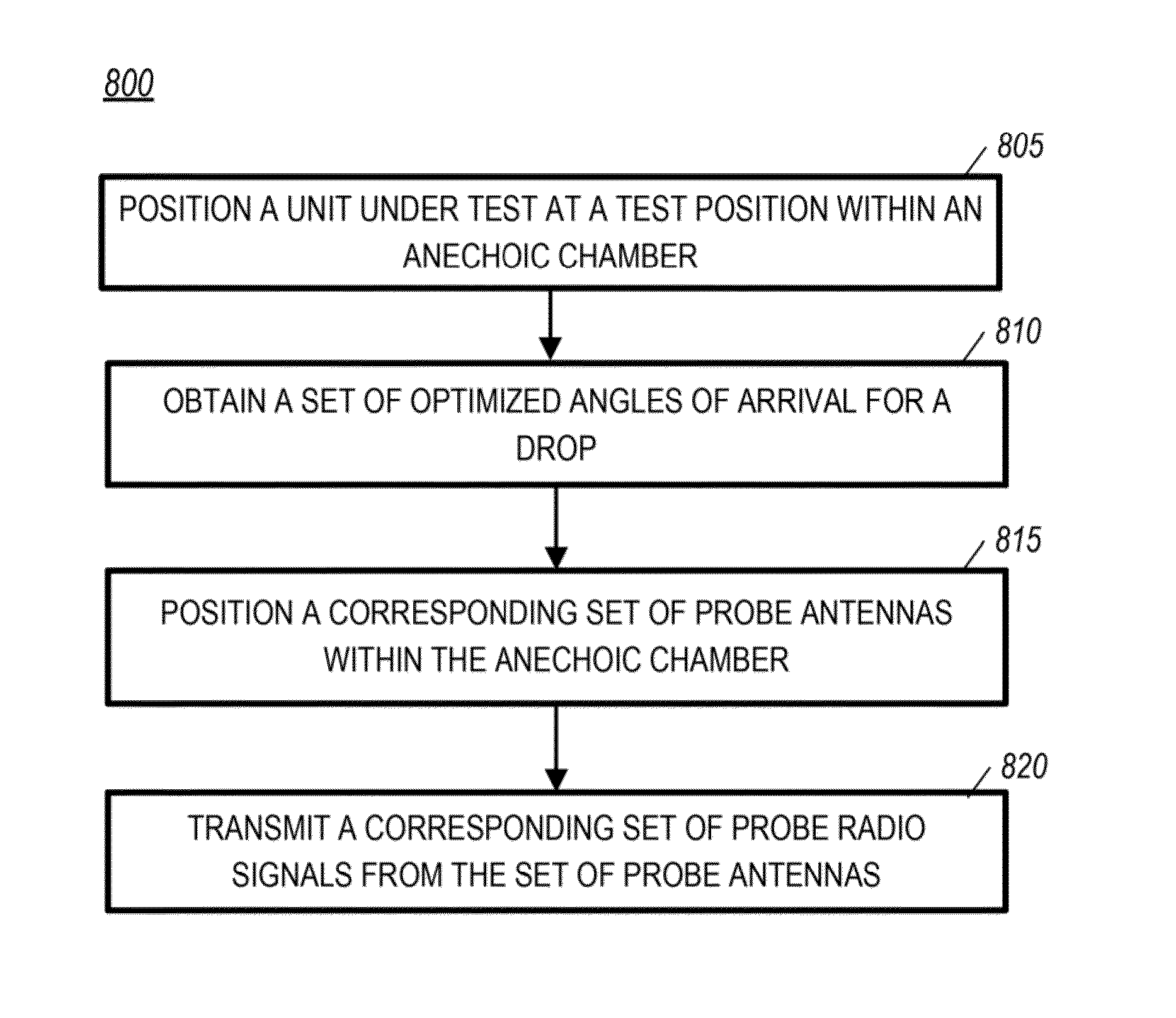
[0013]Before describing in detail the following embodiments, it should be observed that the embodiments reside primarily in combinations of method steps and apparatus components related to testing of wireless devices in an anechoic chamber, in which a minimum number of antenna probes transmit modified forms of a particular test signal to a device under test. Accordingly, the apparatus components and method steps have been represented where appropriate by conventional symbols in the drawings, showing only those specific details that are pertinent to understanding the embodiments of the present invention so as not to obscure the disclosure with details that will be readily apparent to those of ordinary skill in the art having the benefit of the description herein.

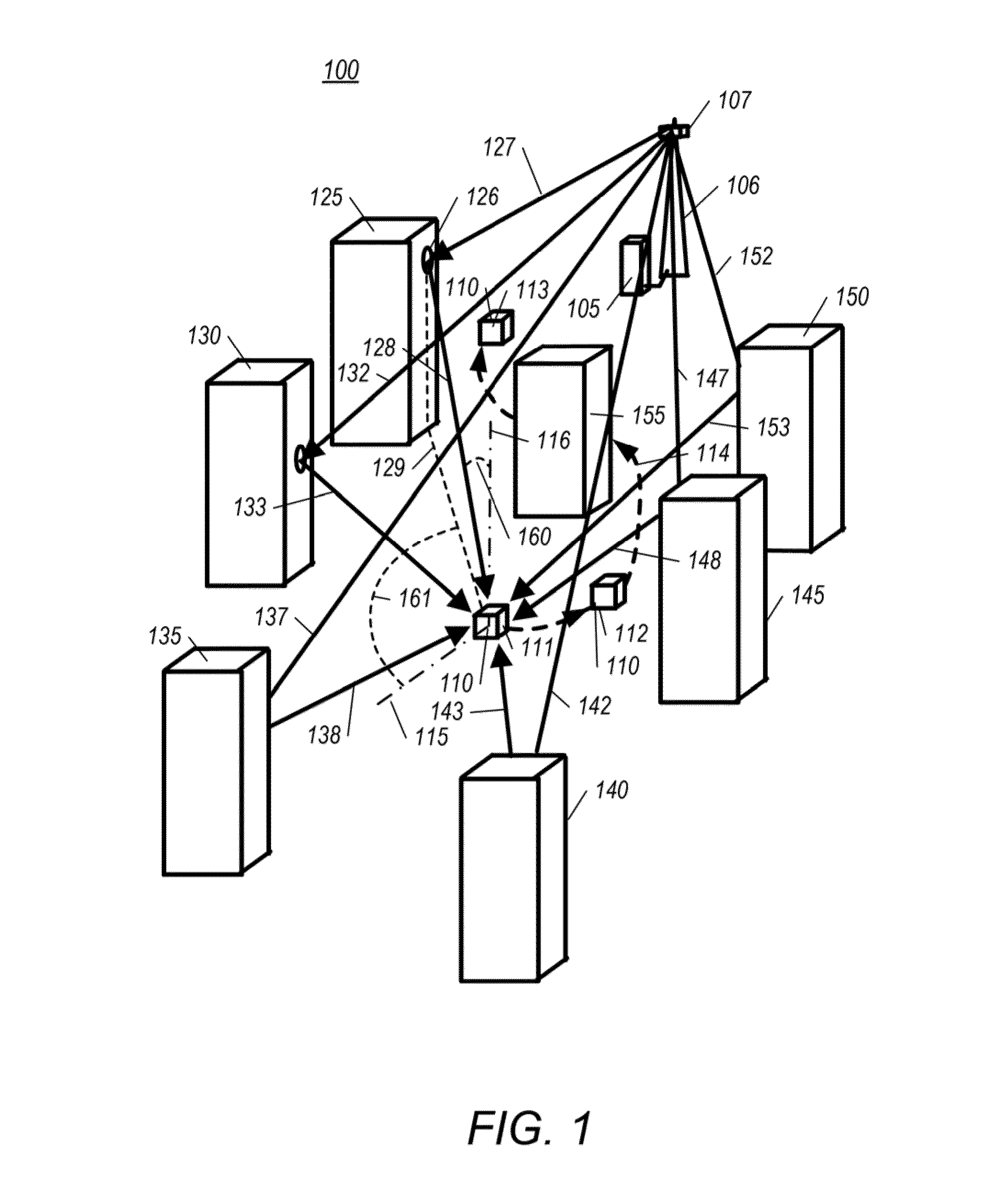
[0014]Referring to FIG. 1, a geometric block diagram of a radio system model 100 that is used as a basis of modeling radio signal propagation in actual radio systems is shown, in accordance with certain embodiments. The radio...


PUM


Abstract

A method and apparatus for obtaining a set of optimized angles of arrival for a corresponding set of radio links. The set of radio links model a radio environment of a wireless unit operating at a particular location within in a radio system. Each radio link represents a different propagation path between the wireless unit and transmitting antenna operating within the radio system. Each optimized angle of arrival represents an angle of arrival of one radio link with reference to the wireless unit. Each probe antenna of a set of probe antennas is positioned at a corresponding angle of the set of optimized angles of arrival. A corresponding set of probe radio signals is transmitted from the set of probe antennas.

Description

FIELD OF THE INVENTION[0001]The present invention relates generally to electromagnetic communications, and more specifically to determining wireless device performance using standardized system modeling.BACKGROUND[0002]Standardized radio system modeling has been used extensively for determining the performance of wireless units, such as vehicular phones, cell phones, laptops, and wireless tablets. Standardized radio system testing provides for comparison of different models of wireless devices and can be useful during development of wireless devices when the standardized system model sufficiently models the real world environment. As systems have become more sophisticated, so have the standardized radio system models. Today there are well defined radio system models that use two dimensional modeling, wherein a wireless device under test is placed at a test position within an anechoic chamber that has a plurality of probe antennas placed at regular intervals at 90 degrees elevation a...

Claims


Application Information

Patent Timeline
Patent Type & Authority Applications(United States)
IPC IPC(8): H04W24/06
CPCH04W24/06H04B17/00H04B17/391H04W88/02
Inventor SZINI, ISTVAN J.KRENZ, ERIC L.PETERS, JOHN R.
Owner GOOGLE TECH HLDG LLC
Why Eureka
Try Eureka