

Lower receiver for firearms
a lower receiver and firearm technology, applied in the field of firearm assemblies, can solve the problems of affecting firing accuracy and speed, affecting the accuracy of firing, and the tedious and slow process of bolt catch roll pin installation and removal, so as to improve the accuracy of installation and removal speed, and address tactical advantages.
- Summary
- Abstract
- Description
- Claims
- Application Information
AI Technical Summary
Benefits of technology
Problems solved by technology
Method used
Image

Examples
Embodiment Construction
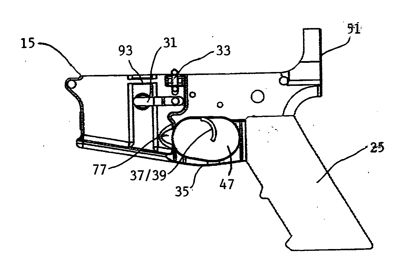
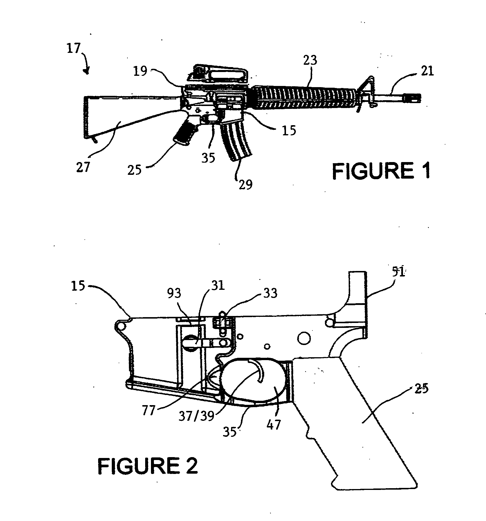
[0029]The improved lower receiver 15 of this invention is illustrated in the FIGURES. FIGS. 1 and 2 show lower receiver 15 in various stages of assembly with other component assemblies of firearm 17. Firearm 17 (as shown herein, an AR-15 type of semi-automatic firearm that is well known in the art) typically includes an upper receiver 19 connected with lower receiver 15. The receivers are made of metal or other materials known for such application using well know manufacturing techniques (milling, molding and the like).
[0030]Upper receiver 19 is adapted for connection of the upper assemblies of firearm 17 thereto (including barrel 21 and handguard set 23, for example) as is well known. Lower receiver 15 is adapted for connection of the lower assemblies of firearm 17, including user interface assemblies 25 and 27 (a pistol grip assembly and a stock assembly, respectively, the stock assembly including the buttstock and buffer tube), magazine 29, magazine catch assembly 31, bolt catch ...
PUM
 Abstract
Description
Claims
Application Information