Heat transfer engine

a heat transfer engine and heat transfer technology, applied in the direction of steam engine plants, machines/engines, lighting and heating apparatus, etc., can solve the problems of limited heat load and distance, general limitation of passive methods, etc., and achieve the effect of reducing the overhead of external power and yielding flexibility in operation

Inactive Publication Date: 2015-04-16
J R THERMAL LLC
View PDF3 Cites 4 Cited by
  • Summary
  • Abstract
  • Description
  • Claims
  • Application Information

AI Technical Summary

Benefits of technology

[0008]The invention is a thermally activated closed loop heat transfer system that alleviates the need for an external power source other than the heat being transferred, thus eliminating the external power overhead associated with motor driven pumps. The system is based on circulating a working fluid with a pump, part of which changes state from liquid to vapor and back, that is driven by an engine. All of the engine's power output is utilized by the pump. The system allows for nearly isothermal heat transport from the heat input to the heat output when pure or azeotropic working fluids are chosen, since the power required to circulate a fluid is miniscule when compared to the heat being transported.
[0009]The system has moving mechanical parts, in the form of a positive displacement engine directly powering a positive displacement pump. The system automatically allows for nearly proportional fluid flow relative to the total heat transported under a set operating condition, since the proportions of fluid passing through the engine and pump are fixed by the displacement ratio of the two devices. The need for external control to adjust the pumping speed is thereby eliminated.
[0010]Varying heat transport distance can readily be accommodated by the present invention, for instance distances of less than lm or greater than 100 m can be accommodated by the same system and same power loads. Also the system can work against gravity, centrifugal forces or other body forces, giving the system flexibility in its applications. The transport distance and ability to work against body forces yields flexibility in operation when compared to passive devices that rely on capillarity or gravity to circulate fluid.

Problems solved by technology

The passive methods are generally limited by heat load, transport distance or orientation, while the active methods require an external power source.
The heat load and distance is most frequently limited by the capillarity of the wick, but can also be limited by the sonic limit, nucleation limit, and entrainment limit.

Method used


Image

  • Heat transfer engine
  • Heat transfer engine
  • Heat transfer engine

Examples


Embodiment Construction

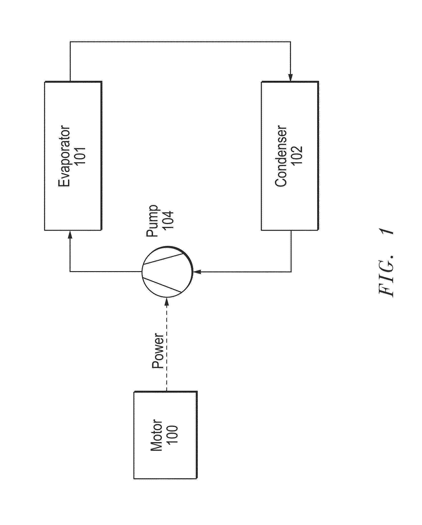
[0022]A typical pumped two-phase closed loop heat transfer system is presented in FIG. 1. This system consists of a motor 100, a pump 104, an evaporator 101, and a condenser 102. The pump 104 which is driven by the motor 100, receives it's liquid from the condenser 102, and delivers the liquid to the evaporator 101. There are three energy exchanges into or out of this system. Electrical energy is input into the motor 100, which is converted into mechanical energy. Thermal energy is input into the evaporator 101, which vaporizes the liquid. Thermal energy is removed from the condenser 102, which condenses the vapor back to liquid.

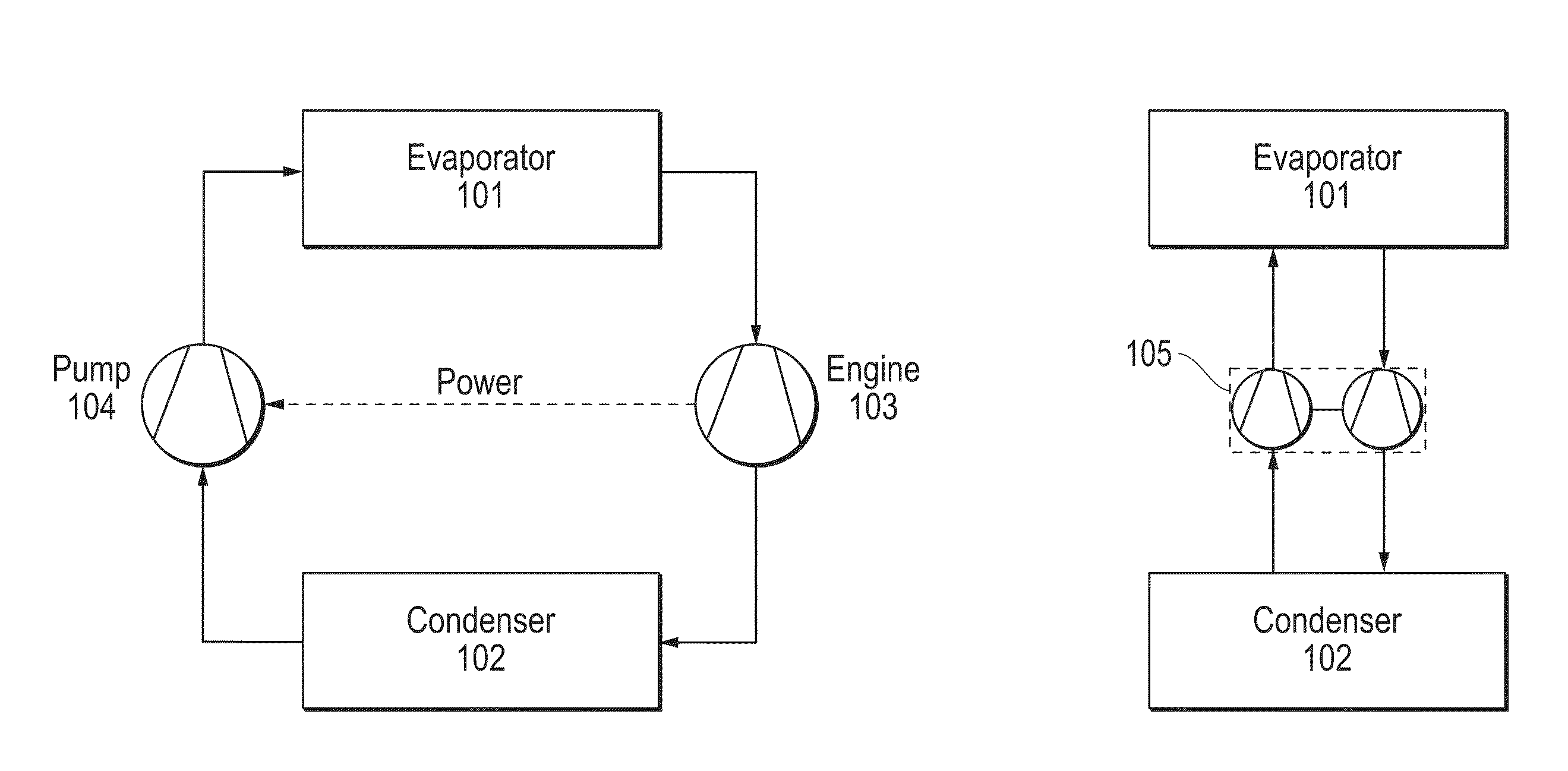
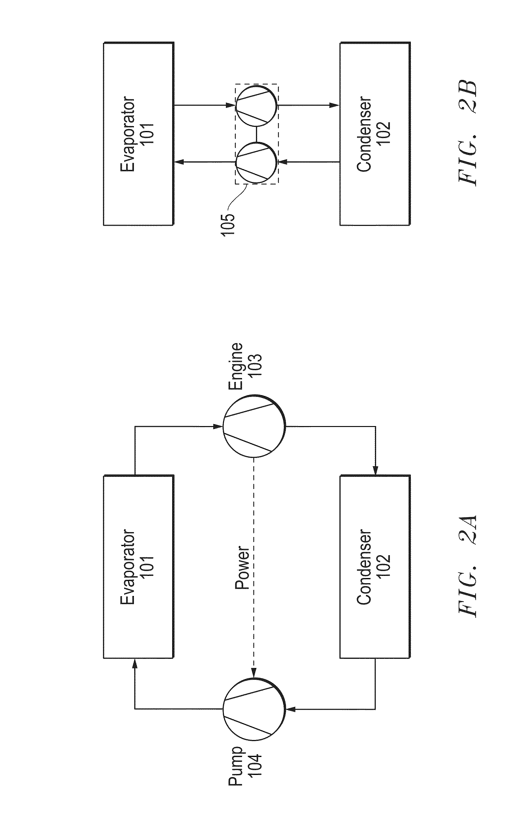
[0023]One embodiment of the present invention is represented in a basic schematic in FIG. 2A, and includes an evaporator 101, a condenser 102, an engine 103 and a pump 104. The engine and pump are both positive displacement devices, and all power generated by the engine 103 drives the pump 104. While the engine 103 is a positive displacement type, it should ...


PUM


Abstract

The invention provides a method for a thermally activated closed loop heat transfer system, and requires no other external power source other than the heat which it is transferring. The system is based on a two-phase (liquid/vapor) working fluid, with heat input through an evaporator and heat rejected through a condenser. All of the mechanical power produced by an engine, driven by the high vapor quality fluid leaving the evaporator, is consumed by the pump. The pump drives the low vapor quality fluid leaving the condenser back to the evaporator. Nearly isothermal heat transport can be achieved when using a pure or azeotropic working fluid, since the operation only requires the evaporator pressure to be marginally higher than the condensers pressure.

Description

PRIORITY STATEMENT UNDER 35 U.S.C. §119[0001]The present U.S. Patent Application claims priority pursuant to 35 U.S.C. §119(e) to U.S. Provisional Application Ser. No. 61 / 890,656, filed Oct. 14, 2013, in the name of Jeremy Rice, entitled “A TWO-PHASE (LIQUID / VAPOR), CLOSED LOOP HEAT TRANSFER SYSTEM WITH A PASSIVE VAPOR DRIVEN PUMP (VDP),” the disclosure of which is hereby incorporated by reference in its entirety.BACKGROUND OF THE INVENTION[0002]There are several existing closed loop heat transfer technologies, including both passive and active methods. The passive methods are generally limited by heat load, transport distance or orientation, while the active methods require an external power source.[0003]Heat pipes are a passive device relying on two-phase heat transfer (evaporation / condensation). The liquid is pumped by capillarity through a continuous wick, from the condenser, to the evaporator. This device is reversible (i.e., the condenser and evaporator can be switched). The h...

Claims


Application Information

Patent Timeline
Patent Type & Authority Applications(United States)
IPC IPC(8): F01K25/08F28D15/02
CPCF01K25/08F28D15/02F28D15/0266
Inventor RICE, JEREMY
Owner J R THERMAL LLC
Why Eureka
Try Eureka