
Technique for view synthesis

a virtual view and view technology, applied in the field of virtual view computing, can solve the problems of inability to change the point of view in post-processing, and the inability to capture images in all directions at the same tim

Active Publication Date: 2015-04-16
TELEFON AB LM ERICSSON (PUBL)
View PDF3 Cites 44 Cited by
  • Summary
  • Abstract
  • Description
  • Claims
  • Application Information

AI Technical Summary

Benefits of technology

The patent describes a method for computing a virtual view based on multiple camera views. The method selects two or three camera views that partially overlap and uses a multilinear relation to relate the camera views to the virtual view. This allows for a view that is not restricted to the view of the camera. The method can also compute the virtual view based on the parameters of the virtual view. The virtual view can be specified by the projection parameters of the virtual view. The method can also use a mesh to indicate the overlapping camera views. The technical effect of the patent is to provide a technique for computing a virtual view that is not restricted to the view of the camera.

Problems solved by technology

For example, the desired view may be a function of time, may depend on the motion of an object captured by the camera, or may even be unpredictable at the time the video is recorded.
However, a conceptual limitation of the first group of devices is the inability to capture images in all directions simultaneously.
Furthermore, the point of view cannot be changed in post-processing.
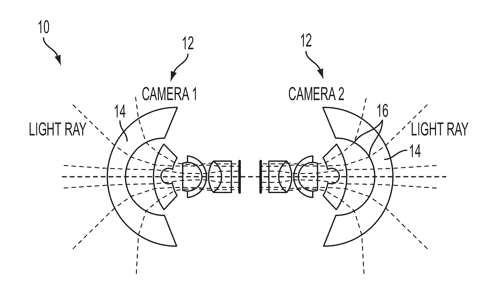
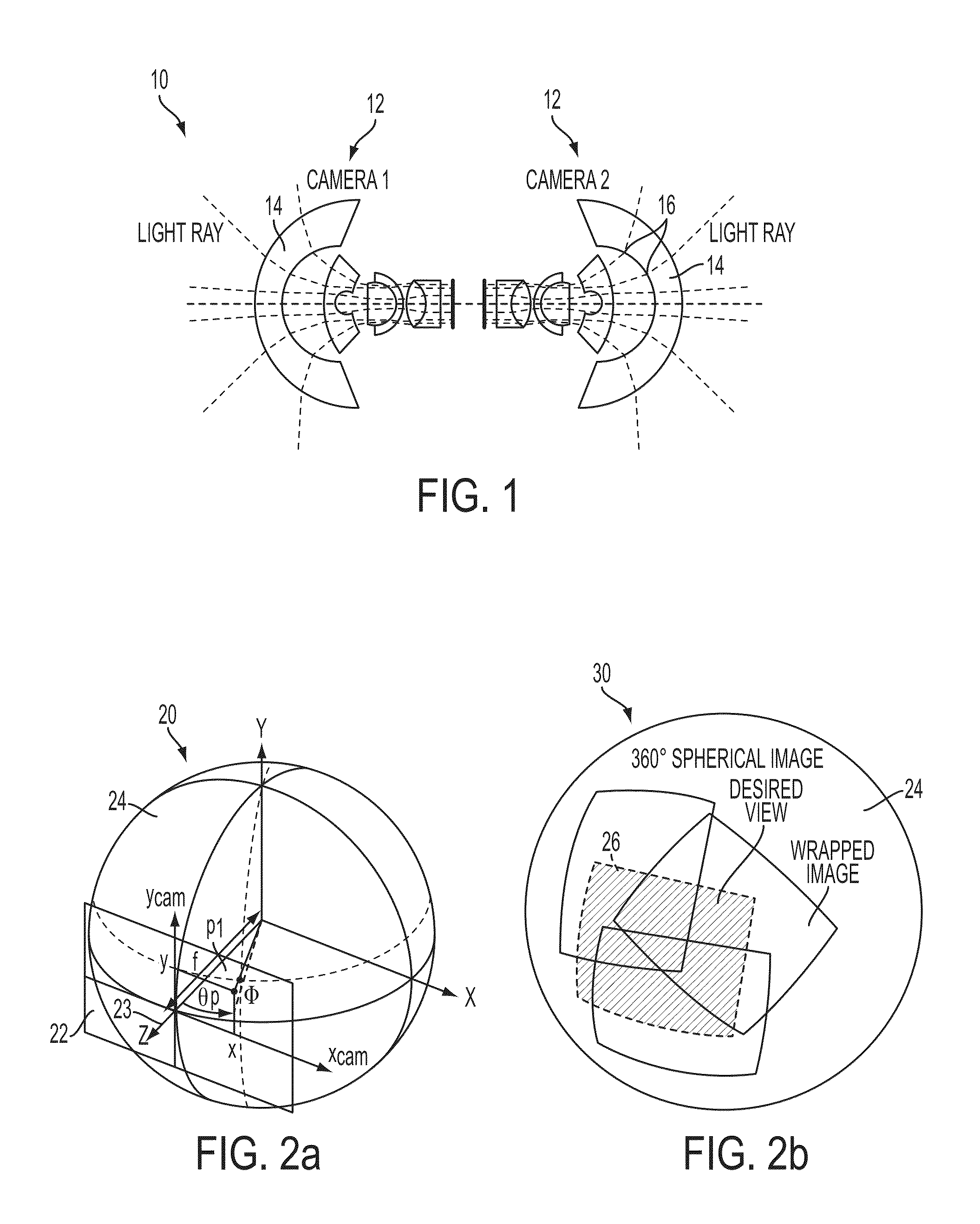
A major disadvantage of fisheye lenses is the non-linear distortion 16 of the image in the radial direction causing a decreasing resolution towards the image periphery.
It is not possible to map each pixel in the image resulting from a fisheye lens onto a projection plane of a defined view.
The disadvantages of using such convex mirrors are similar to those of the fisheye lenses.
However, stitching a plurality of images combines different views into one image leading to an optically inconsistent image.
Furthermore, image stitching does not provide a view that is different from any one of the camera views.
In a real device, however, it is not feasible that all the camera images are projected onto the same spherical surface 24.
Otherwise, any slight misalignment causes a significant mismatch between the projected images, which in turn affects the cropped image.
Furthermore, the non-linear projective transformation 20 of pixel coordinates does not allow directly synthesizing the multiple images by means of a linear mapping operation.
Therefore, computation-time costly image stitching algorithms have to be used, which is undesirable for real-time operation, particularly in the context of mobile devices.

Method used


Image

  • Technique for view synthesis
  • Technique for view synthesis
  • Technique for view synthesis

Examples


first embodiment

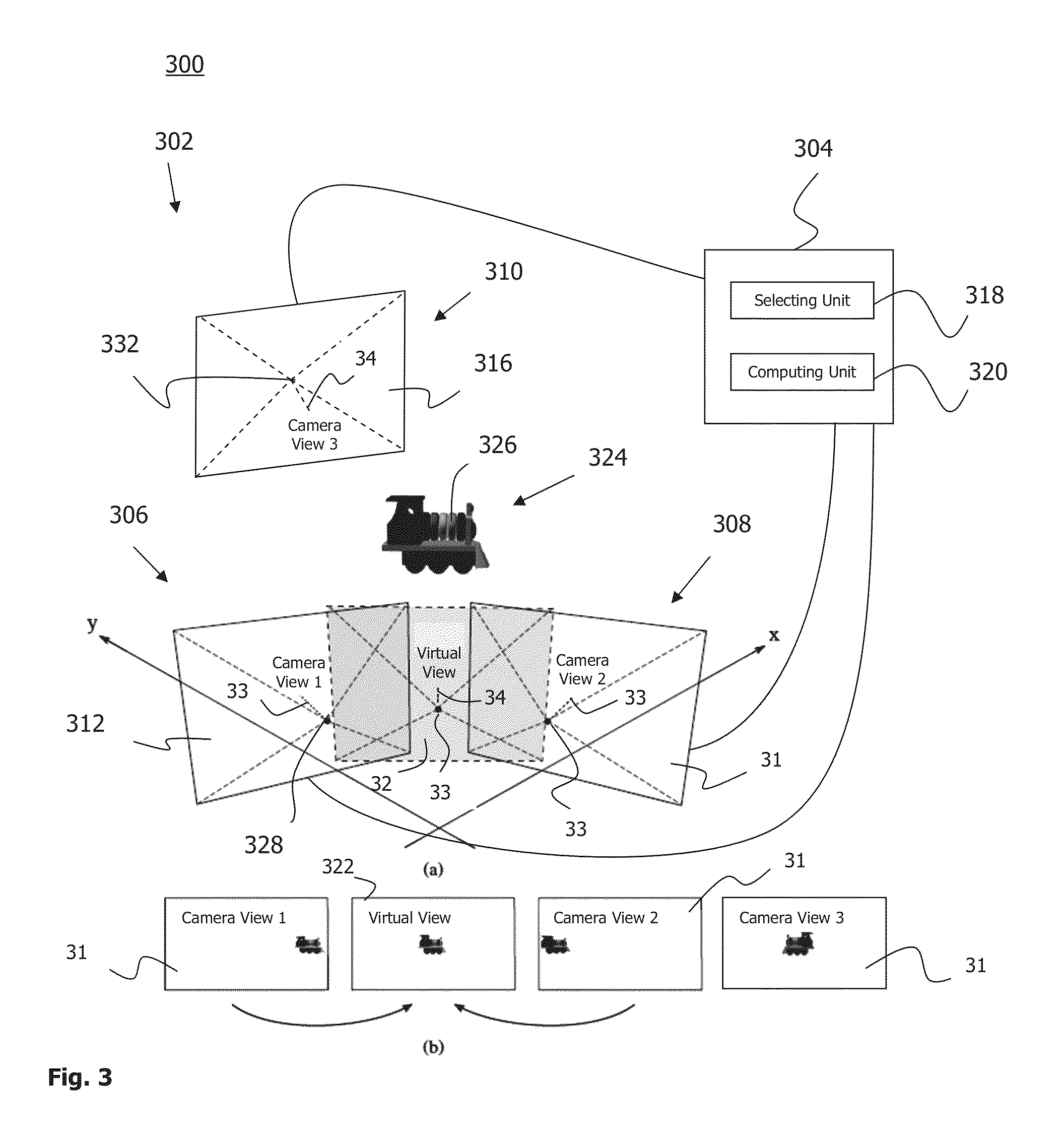
[0109]In the method 400, the multilinear relation relating the selected camera views and the desired virtual view 322 is computed based on the parameters of the virtual view 322. For example, the multilinear relation is parameterized, i.e., the multilinear relation is computed as a function of the parameters of the virtual view 322. For computing the virtual view 322 for a certain set of parameters of the virtual view 322, coefficients representing the multilinear relation are evaluated once for each part of the partition. The coefficients of the multilinear relation are applied for a plurality of pixels, including at least the pixels belonging to the corresponding part of the partition.

second embodiment

[0110]In the method 400, the multilinear relation is computed based on the projection matrices, P, of the selected camera views and the virtual view 322. For example, the multilinear relation for combining three views, e.g., two camera views 312 and 314 and one virtual view 322, is representable by a trifocal tensor, T (P312, P314, P322). The trifocal tensor, T, is applied, if the virtual view 322 is on one of the edges in the mesh 1000, e.g., on the edge 1006-7. The multilinear relation relating four different views, e.g., three camera views 312, 314 and 316 and one virtual view 322, is representable by a quadrifocal tensor, Q (P312, P314, P316, P322). The quadrifocal tensor, Q, is applied, if the virtual view 322 is within one of the parts of the partition, e.g., within the part 1004-2.

[0111]At least the projection matrix, P322, of the virtual view 322 is parameterized. By computing the multilinear relation as a function of the projection matrices of the related views, the multili...


PUM


Abstract

A technique for computing an image of a virtual view based on a plurality of camera views is presented. One or more cameras provide the plurality of camera views. As to a method aspect of the technique, two or three camera views that at least partially overlap and that at least partially overlap with the virtual view are selected among the plurality of camera views. The image of the virtual view is computed based on objects in the selected camera views using a multilinear relation that relates the selected camera views and the virtual view.

Description

CROSS-REFERENCE TO RELATED APPLICATION(S)[0001]This application claims priority to European Patent Application 13004900.0 filed on Oct. 11, 2013, which is incorporated by reference herein.TECHNICAL FIELD[0002]The presented disclosure generally relates to a technique for computing a virtual view based on a plurality of camera views. In particular, and without limitation, the present disclosure relates to a method and a device for computing an image of a virtual view based on at least partially overlapping camera views, wherein the virtual view is different from each of the camera views.BACKGROUND[0003]Vision implies a reduction of a scene, which is actually three-dimensional, to a view providing a certain perspective of the scene. The view is substantially a projection of the three-dimensional scene onto a two-dimensional surface, such as the human retina or the photosensitive surface of a chip. The view is a reduction of the full three-dimension scene to a two-dimensional image of o...

Claims


Application Information

Patent Timeline
IPC IPC(8): H04N5/232H04N5/225
CPCH04N5/23238H04N5/2258G06T15/205H04N23/698H04N23/90H04N23/45
Inventor DJORDJEVIC, BRANKOCAGMAN, CANLANGER, ALEXANDER
Owner TELEFON AB LM ERICSSON (PUBL)
Learn More