Power supply control apparatus, image processing apparatus, and non-transitory computer readable medium
Active Publication Date: 2015-04-16
FUJIFILM BUSINESS INNOVATION CORP
View PDF6 Cites 14 Cited by
Summary
Abstract
Description
Claims
Application Information
AI Technical Summary
This helps you quickly interpret patents by identifying the three key elements:
Problems solved by technology
Method used
Benefits of technology
Benefits of technology
The invention is a power supply control apparatus that includes a sensor, two imaging units, and a state controller. The sensor senses a person when the apparatus is in a power saving state. The first imaging unit consumes higher power than the sensor and captures an image of a person approaching. The second imaging unit captures an image used to recognize a person. The state controller causes the first and second imaging units to be in a power supply state in case the sensor has sensed a person. The technical effect of this invention is to improve the accuracy and efficiency of power supply control by using sensors and imaging units to detect and recognize people, and to automatically activate the power supply in a timely manner.
Problems solved by technology
The first imaging unit consumes higher power than the sensor and captures an image of a person approaching.
Method used
Image
Click on the blue label to locate the original text in one second.
Reading with bidirectional positioning of images and text.
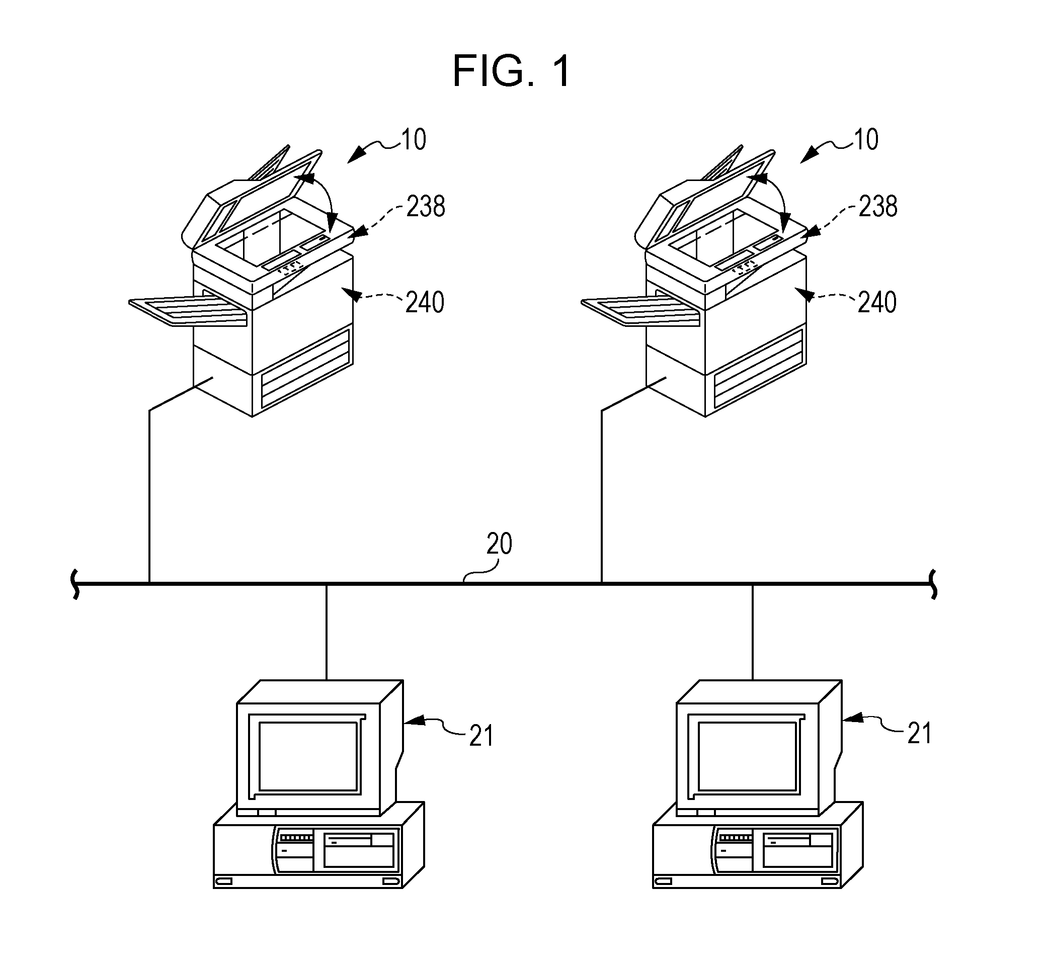
[0026]As illustrated in FIG. 1, an image processing apparatus 10 according to the first exemplary embodiment is connected to a network-communication network 20 such as the Internet. In FIG. 1, two image processing apparatuses 10 are connected to the network-communication network 20; however, the number of image processing apparatuses 10 is not limited thereto, and may be one or be three or more.
[0027]Moreover, plural personal computers (PCs) 21 functioning as information terminal devices are connected to the network-communication network 20. In FIG. 1, two PCs 21 are connected to the network-communication network 20; however, the number of PCs 21 is not limited thereto, and may be one or be three or more. Moreover, the information terminal devices are not limited to the PCs 21. Additionally, wired connection does not necessarily need to be used for the network-communication network 20. In other words, the network-communication network 20 ma...
second embodiment
[0162]In the following, a second exemplary embodiment will be described. In the second exemplary embodiment, description of a configuration the same as that of the first exemplary embodiment will be omitted.
[0163]A characteristic of the second exemplary embodiment is a timing at which power is supplied to the recognition camera 30 (the recognition camera 30 is energized). The other configuration and operation are the same as those of the first exemplary embodiment.
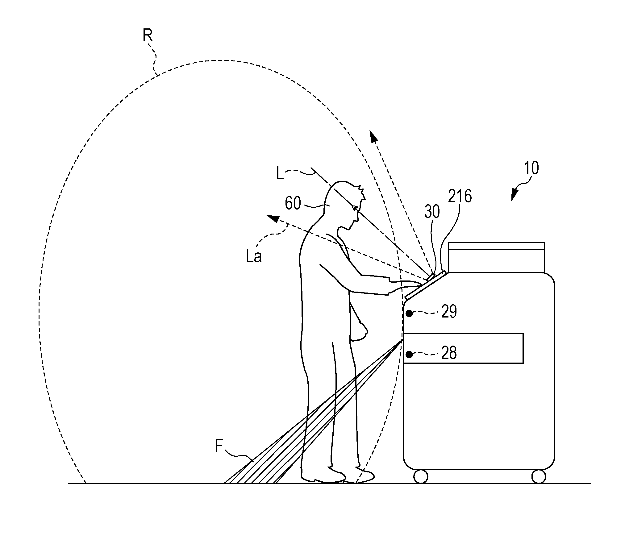
[0164]In the following, a power-supply control routine according to the second exemplary embodiment will be described in accordance with a flowchart illustrated in FIG. 15. In the power-supply control routine, the person presence sensor 28, the access camera 29, and the recognition camera 30 cooperate with each other.
[0165]The processing procedure illustrated in FIG. 15 is started when the image processing apparatus 10 enters the sleep mode. While the image processing apparatus 10 is in the sleep mode, no power is supplied...
example 1
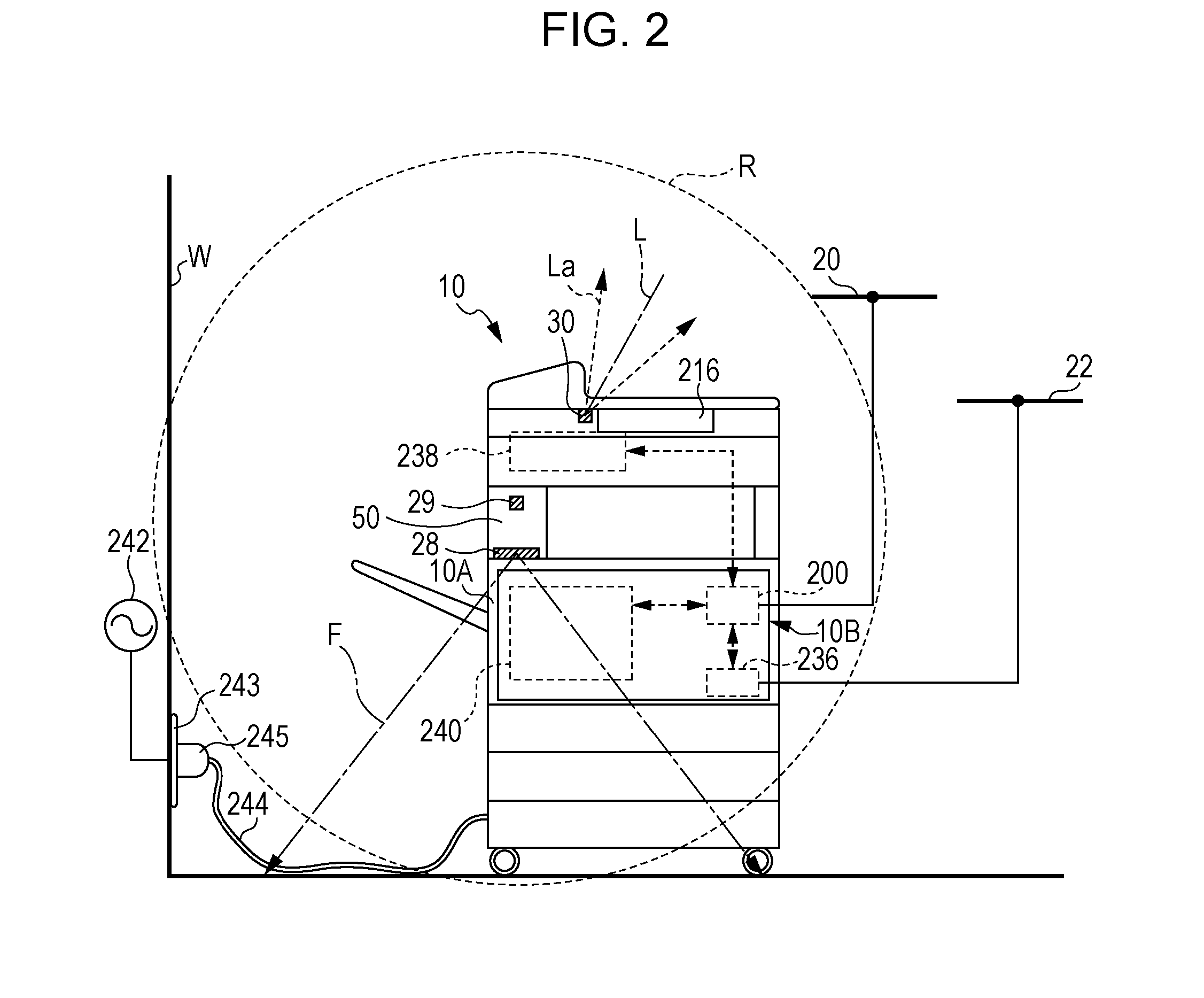
[0205]Central control is performed by the main controller 200 for devices such as the image forming unit 240, the image reading unit 238, the facsimilecommunication control circuit 236, the UI touch panel 216, and the like. The image processing apparatus 10 has a partial power saving function through which devices that are not being used and the main controller 200 are individually made to enter a sleep state.
PUM
Abstract
A power supply control apparatus includes a sensor, a first imaging unit, a second imaging unit, and a state controller. The sensor senses a person when the power supply control apparatus is in a power saving state. The first imaging unit consumes higher power than the sensor and captures an image of a person approaching. The second imaging unit captures an image used to recognize a person. The state controller causes the first imaging unit and the second imaging unit to be in a power supply state in a case where the sensor has sensed a person.
Description
CROSS-REFERENCE TO RELATED APPLICATIONS[0001]This application is based on and claims priority under 35 USC 119 from Japanese Patent Application No. 2013-214902 filed Oct. 15, 2013.BACKGROUND[0002](i) Technical Field[0003]The present invention relates to a power supply control apparatus, an image processing apparatus, and a non-transitory computer readable medium.[0004](ii) Related Art[0005]Person presence sensor control is a way to automate power supply saving control for devices that are power supply targets.SUMMARY[0006]According to an aspect of the invention, there is provided a power supply control apparatus including a sensor, a first imaging unit, a second imaging unit, and a state controller. The sensor senses a person when the power supply control apparatus is in a power saving state. The first imaging unit consumes higher power than the sensor and captures an image of a person approaching. The second imaging unit captures an image used to recognize a person. The state contr...
Claims
Application Information
Patent Timeline
Application Date:The date an application was filed.
Publication Date:The date a patent or application was officially published.
First Publication Date:The earliest publication date of a patent with the same application number.
Issue Date:Publication date of the patent grant document.
PCT Entry Date:The Entry date of PCT National Phase.
Estimated Expiry Date:The statutory expiry date of a patent right according to the Patent Law, and it is the longest term of protection that the patent right can achieve without the termination of the patent right due to other reasons(Term extension factor has been taken into account ).
Invalid Date:Actual expiry date is based on effective date or publication date of legal transaction data of invalid patent.

