Video Laryngoscope with Adjustable Handle Mounted Monitor

a technology of laryngoscope and adjustable handle, which is applied in the field of medical devices, can solve the problems of affecting the safety of patients, affecting the patient's health, and affecting the patient's comfort, and achieves the effect of increasing patient safety and being convenient to s

Inactive Publication Date: 2015-04-23
DONALDSON JILL
View PDF14 Cites 23 Cited by
  • Summary
  • Abstract
  • Description
  • Claims
  • Application Information

AI Technical Summary

Benefits of technology

[0018]In view of the foregoing disadvantages inherent in the known types of video laryngoscope now present in the prior art, the present invention provides a new easily visible display unit wherein the same can be utilized for providing increased patient safety and added convenience for the user when checking on the progress of intubation during a procedure.
[0019]The present invention is a video laryngoscope with a repositionable display screen. The device comprises a handle member and one or more removable blades that removably secure to the handle member, and a display screen mounted to the handle member via a flexible arm. Blades are interchangeably secured to the handle member, enabling a physician to switch out blades according to patient anatomy, without having to have multiple laryngoscopes. This feature provides modular flexibility to the device and reduces cost, as well as the number of laryngoscopes a facility must own.
[0021]During an intubation procedure, the physician holds the device by the handle and manipulates it in different directions to open the tracheal passages. The procedure can involve a great deal of twisting and rotation of the laryngoscope. To ensure that the physician is always able to obtain an easily viewable image of the patient anatomy, the display screen is attached to the handle member via a flexible arm. The physician can use his or her free hand to bend and manipulate the display screen into a desired position. In this way, the medical professional can maintain constant supervision over the tracheal passages.
[0024]Another object of the present invention is to provide a means for enabling physicians intubating a patient to monitor the anatomical environment surrounding a laryngoscope blade.
[0027]A further object of the present invention is to provide a video laryngoscope that may be readily fabricated from materials that permit relative economy and are commensurate with durability.

Problems solved by technology

The procedure can involve a great deal of twisting and rotation of the laryngoscope.

Method used


Image

  • Video Laryngoscope with Adjustable Handle Mounted Monitor
  • Video Laryngoscope with Adjustable Handle Mounted Monitor
  • Video Laryngoscope with Adjustable Handle Mounted Monitor

Examples


Embodiment Construction

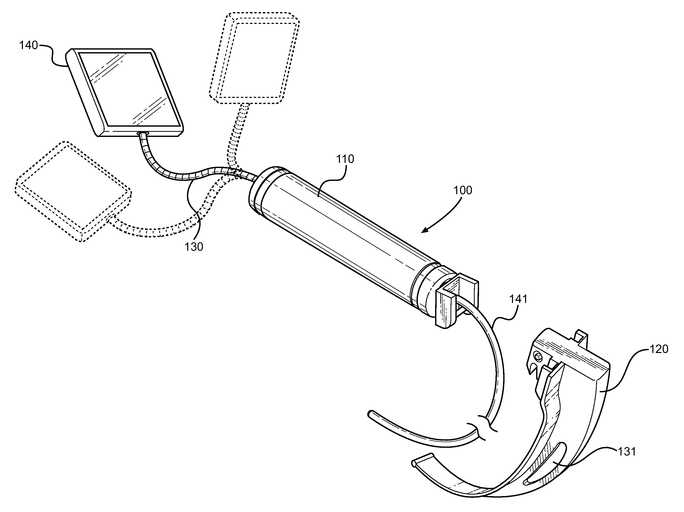
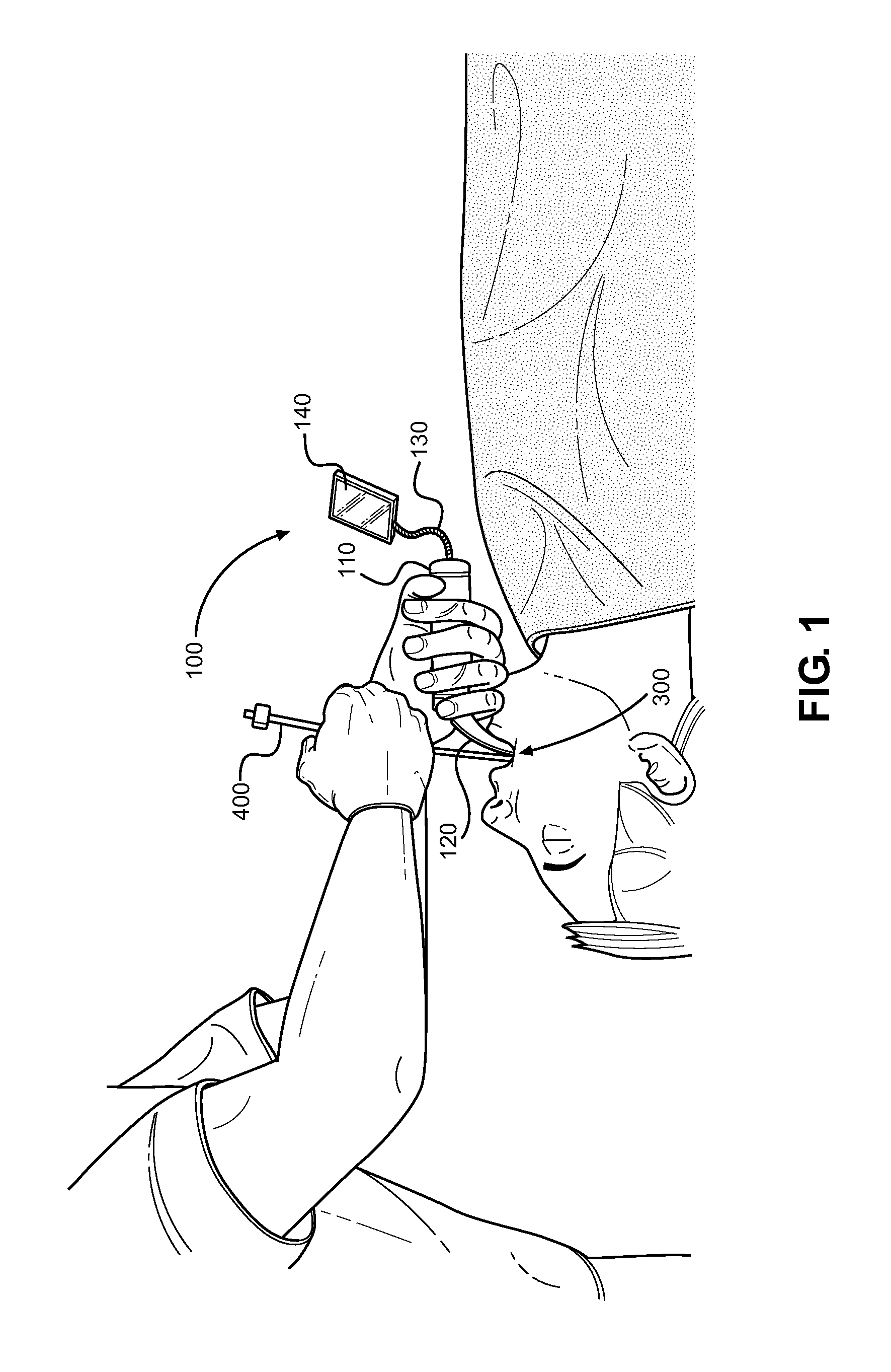
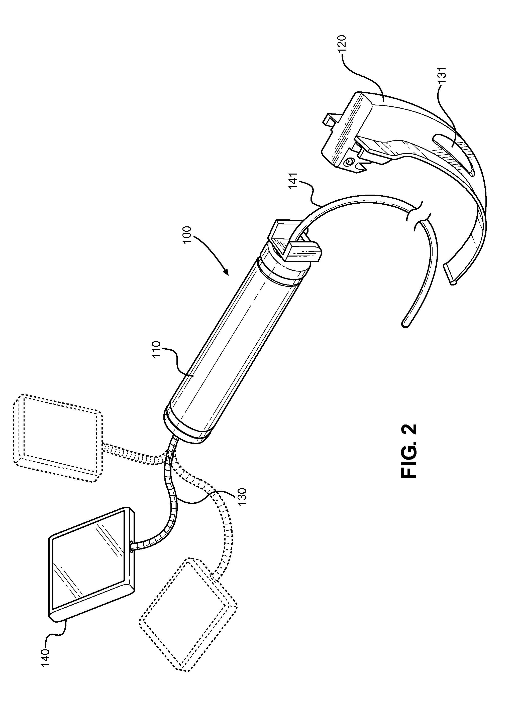
[0033]Reference is made herein to the attached drawings. Like reference numerals are used throughout the drawings to depict like or similar elements of the video laryngoscope. For the purposes of presenting a brief and clear description of the present invention, the preferred embodiment will be discussed as used for aiding in intubation of patients. The figures are intended for representative purposes only and should not be considered to be limiting in any respect.

[0034]Referring now to FIG. 1, there is shown a video laryngoscope according to the present invention, in use. A physician grips the laryngoscope 100 by the handle member 110. One of a plurality of interchangeable blade members 120 is removably secured to a first end of the handle member. The blade is inserted into the patient's oral cavity 300, where it holds the tracheal passages open to permit insertion of a length of tubing 400. Blade members may be curved, as shown, or straight, to accommodate different intubation pro...


PUM


Abstract

Provided is a video laryngoscope having a repositionable display screen. The screen is secured via a flexible arm to the outermost area of the handle member second end. This flexible arm may be flexible metal conduit to enable support of the display screen and manipulation of position. A plurality of blade members of differing sizes and material construction may secure individually to the end of the handle member opposing the flexible arm. The blade members are removable. A length of fiber optic cable runs from the display screen, through the handle member and is inserted through an aperture in the blade member. The lens of a fiber optic camera, and a light source are disposed at a free end of the cable to provide video feedback of the environment near the working end of the blade member during a laryngoscopy procedure.

Description

CROSS REFERENCE TO RELATED APPLICATION[0001]This application claims the benefit of U.S. Provisional Application No. 61 / 893,511 filed on Oct. 21, 2013 entitled “Laryngoscope with Camera and Handle Monitor.” The above identified patent application is herein incorporated by reference in its entirety to provide continuity of disclosure.BACKGROUND OF THE INVENTION[0002]1. Field of the Invention[0003]The present invention relates to medical devices. More particularly, it relates to a medical device used to aid in intubating a patient. The device is a laryngoscope with a flexible camera at the working end to visualize or record footage of the patient's anatomy. A small display is mounted to the handle and is connected to the camera to enable the medical professional to monitor the progress of intubation.[0004]Endotracheal intubation (intubation) involves the insertion of flexible tubing into the trachea to establish an artificial air pathway, or provide a conduit for the administration of ...

Claims


Application Information

Patent Timeline
Patent Type & Authority Applications(United States)
IPC IPC(8): A61B1/00A61M16/04A61B1/07A61B1/06A61B1/267A61B1/05
CPCA61B1/00048A61B1/267A61B1/00052A61B1/051A61M16/0488A61B1/00032A61B1/00117A61B1/07A61B1/0676A61B1/00066
Inventor DONALDSON, JILL
Owner DONALDSON JILL
Why Eureka
Try Eureka