
Optical touch system, method of touch detection, and computer program product

a touch detection and optical technology, applied in the field of optical touch systems, a touch detection method and a computer program product, can solve the problems of inconvenient and time-consuming user operations, inability to integrate the touch function to such a large screen, and limited application of capacitive touch screens, etc., to achieve accurate determining the group transformation

Active Publication Date: 2015-04-30
WISTRON CORP
View PDF2 Cites 2 Cited by
  • Summary
  • Abstract
  • Description
  • Claims
  • Application Information

AI Technical Summary

Benefits of technology

The disclosure describes an optical touch system that can accurately detect touch when two groups of objects approach a base plane. The system uses sensors to create signals in front of the base plane and a processing unit converts those signals into a two-dimensional space. The processing unit analyzes the signals to determine the transformation of the groups of objects, which in turn activates different functions. This means that users can perform required operations at any position in front of the base plane, without being limited to a specific position. This makes it more convenient and efficient for users, especially when the base plane is very large.

Problems solved by technology

In conventional resistive, capacitive and rear projection touch screens, the capacitive touch screen has a best touch effect, though the cost thereof is the highest, and along with increase of screen size, application of the capacitive touch screen is limited.
It is not easy to integrate the touch function to such large screen since regardless of a type of an operating interface, function keys or shortcuts are generally disposed at the edge of the screen, so as to avoid influencing content displayed at the center of the screen.
Moreover, since the screen is excessively large, it is inconvenient and time-consuming for the user to perform operations thereon.

Method used


Image

  • Optical touch system, method of touch detection, and computer program product
  • Optical touch system, method of touch detection, and computer program product
  • Optical touch system, method of touch detection, and computer program product

Examples


Embodiment Construction

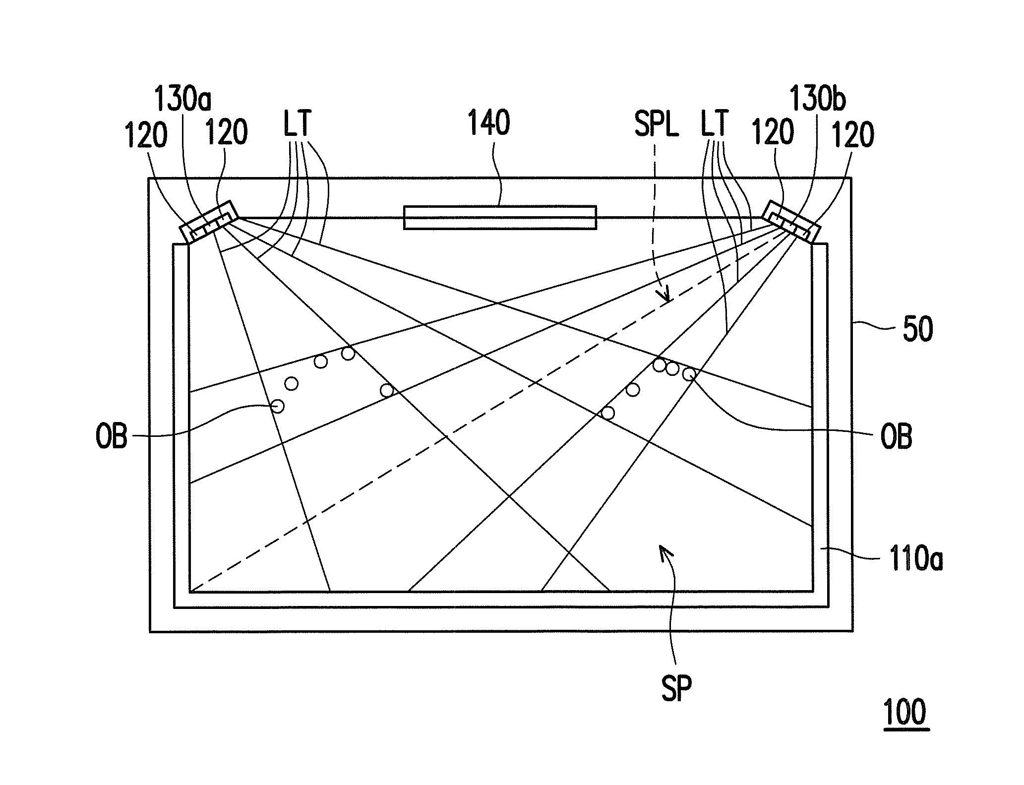
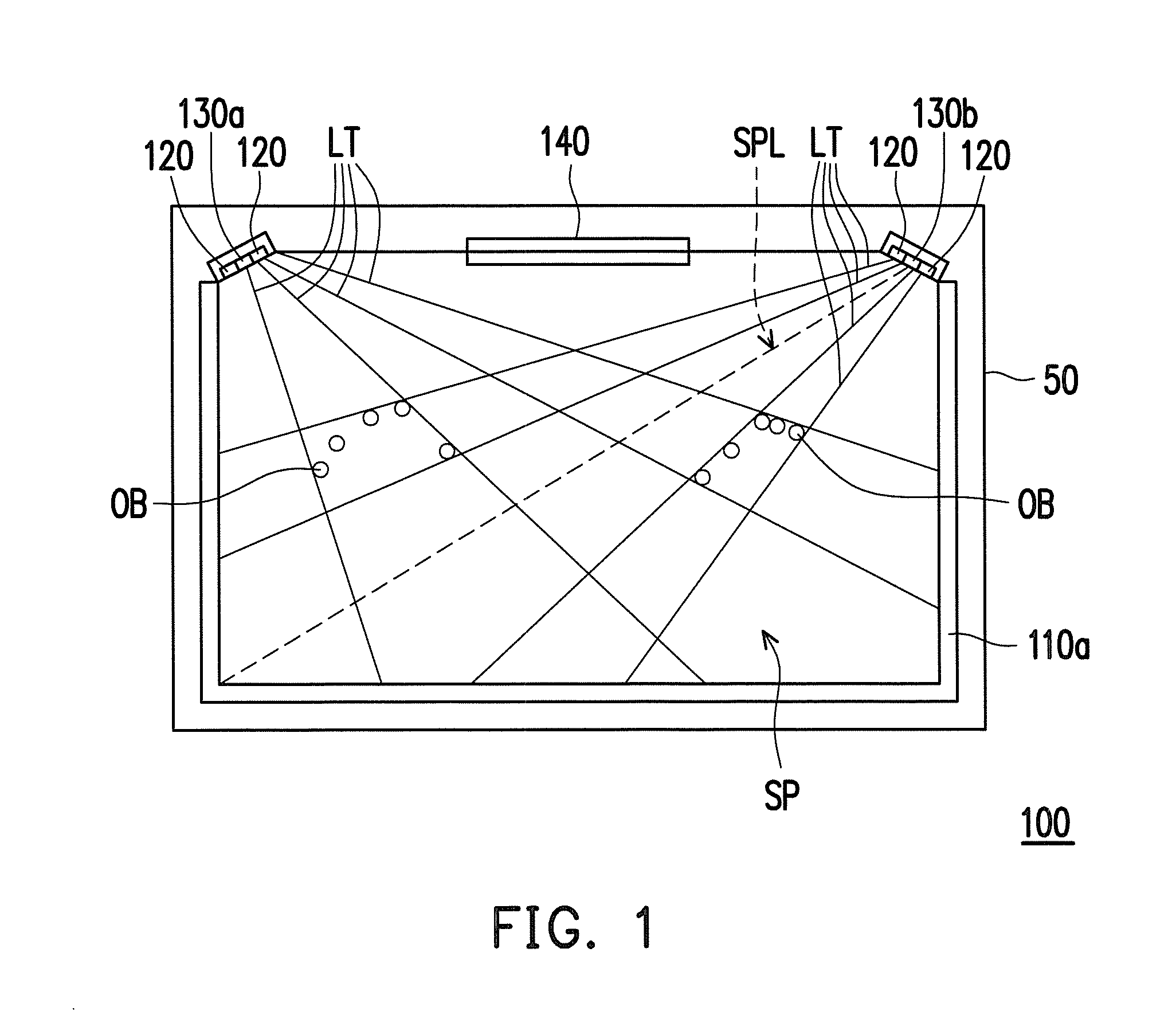
[0033]FIG. 1 is a schematic diagram of an optical touch system according to an embodiment of the disclosure. Referring to FIG. 1, the optical touch system 100 of the present embodiment can be used to determine a group transformation when two groups of objects OB approach to or touch a base plane SP. In the present embodiment, the optical touch system 100 can be applied to a display 50, where the base plane SP is a display surface of the display 50. Alternatively, in other embodiments, the base plane SP can also be a surface of a touch platform different to the display 50, where the touch platform is, for example, a touchpad (for example, a touchpad on a keyboard of a notebook computer or a touchpad on other handheld electronic apparatus), a desktop, a wall surface or other surfaces suitable for being approached or touched by the two groups of the objects OB. In the present embodiment, the two groups of the objects OB are two hands of the user, and the group transformation is gesture...


PUM


Abstract

An optical touch system is provided. At least one light source is disposed at a side of a base plane. A first optical sensor and a second optical sensor detect a space in front of the base plane to generate a first signal and a second signal. When two groups of objects approach to or touch the base plane, a processing unit determines at least one first portion of the first signal corresponding to the two groups of the objects and at least one second portion of the second signal corresponding to the two groups of the objects, and converts the at least one first portion and the at least one second portion into a plurality of touch regions, and determines group transformations according to positions corresponding to at least part of touch regions. Additionally, a method of touch detection, and a computer program product are also provided.

Description

CROSS-REFERENCE TO RELATED APPLICATION[0001]This application claims the priority benefit of Taiwan application serial no. 102138748, filed on Oct. 25, 2013. The entirety of the above-mentioned patent application is hereby incorporated by reference herein and made a part of this specification.BACKGROUND[0002]1. Technical Field[0003]The disclosure relates to an optical touch system, a method of touch detection and a computer program product.[0004]2. Related Art[0005]In recent years, as a touch electronic product has advantages of easy operation and high operation intuition, it is well received by consumers and becomes a main stream in the market. In conventional resistive, capacitive and rear projection touch screens, the capacitive touch screen has a best touch effect, though the cost thereof is the highest, and along with increase of screen size, application of the capacitive touch screen is limited.[0006]In order to seek an alternative scheme of the capacitive touch screen, an opti...

Claims


Application Information

Patent Timeline
Patent Type & Authority Applications(United States)
IPC IPC(8): G06F3/042
CPCG06F3/0421G06F3/038G06F3/0425
Inventor HSIEH, SHENG-HSIENSU, SHANG-CHINCHANG, HSUN-HAOCHENG, KAI-CHUNGWEI, SHOU-TE
Owner WISTRON CORP
Learn More