

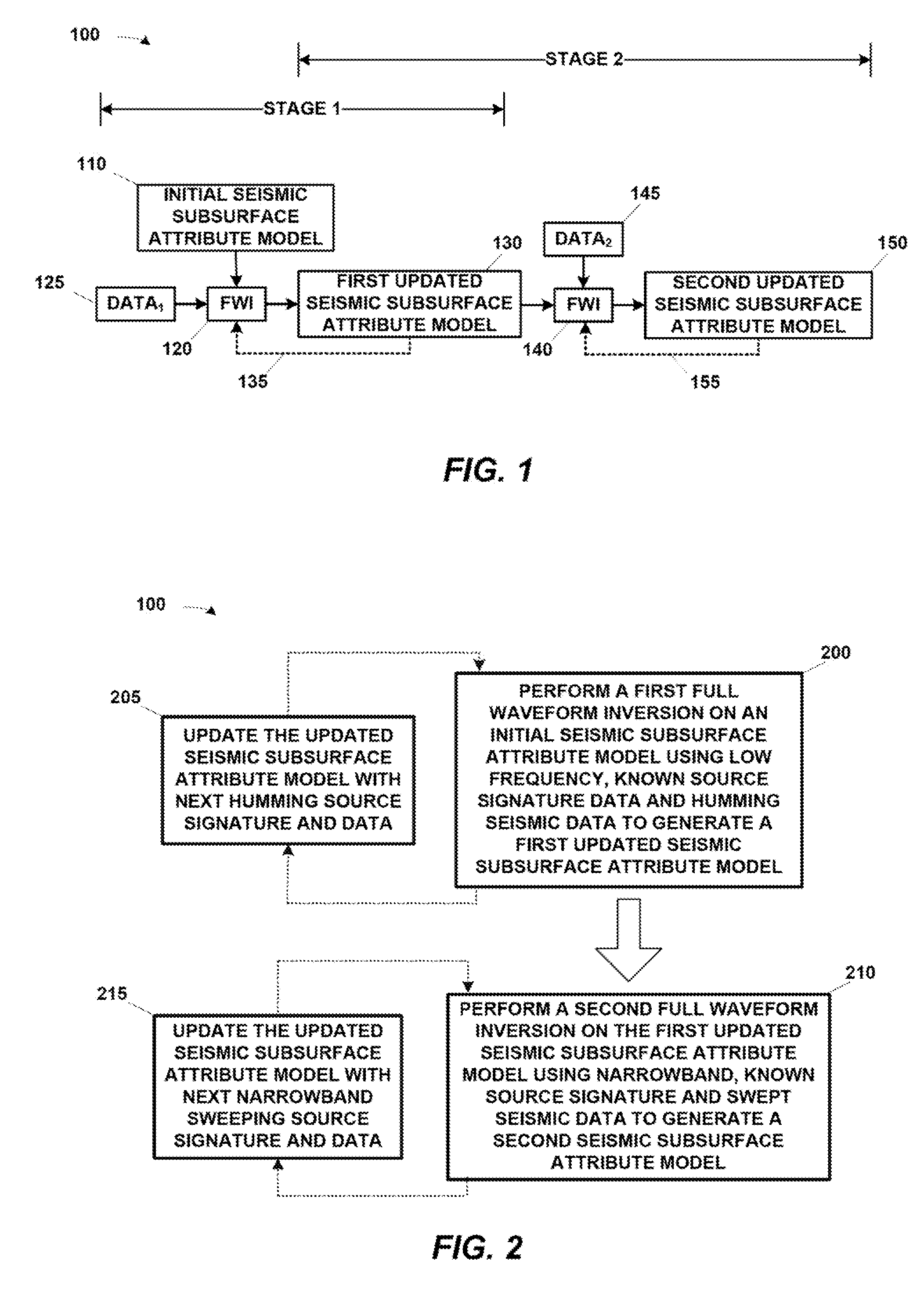
Two stage seismic velocity model generation
a seismic velocity model and two-stage technology, applied in the field of seismic data processing and analysis, can solve the problems of increasing the background noise of the earth, affecting the search for hydrocarbons and other fluids, and affecting the acquisition of seismic data,
- Summary
- Abstract
- Description
- Claims
- Application Information
AI Technical Summary
Benefits of technology
Problems solved by technology
Method used
Image

Examples
Embodiment Construction
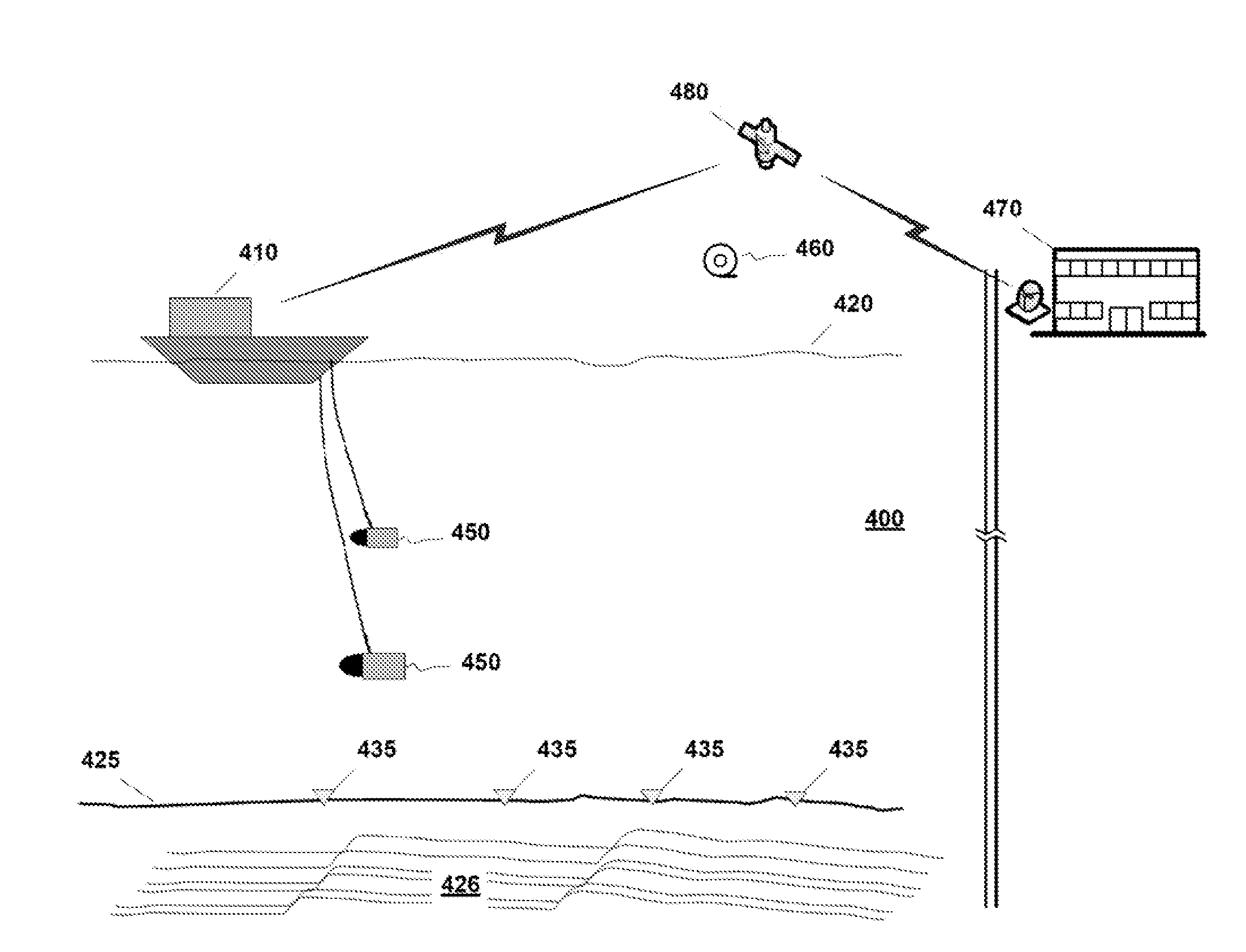
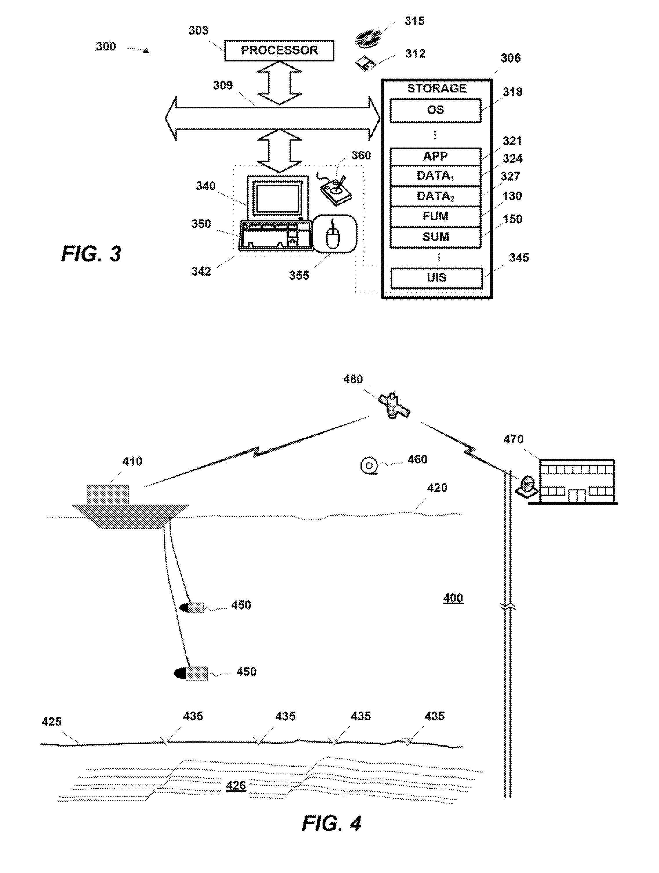
[0026]Accurate subsurface attribute models provide good seismic images of the subsurface. The presently disclosed technique is a method for improving acquisition, processing, and in particular subsurface attribute model building in an environment where the signal-to-noise ratio rapidly decreases at progressively lower frequencies. We define “low frequencies” as “frequencies below which getting sufficient signal-to-noise with conventional airgun sources rapidly becomes more difficult as the frequency decreases”, i.e., below about 6-8 Hz.
[0027]One strategy for acquiring data as described above uses a controlled-frequency source to generate a narrow-bandwidth signal. This concentrates the source's power into a narrower frequency bandwidth, thereby increasing the signal-to-noise over that narrow bandwidth. In general “narrow bandwidth” means less than two octaves, although in some embodiments it may be up to three octaves. See U.S. application Ser. No. 13 / 327,524, filed Dec. 15, 2011.
[0...
PUM
 Abstract
Description
Claims
Application Information