Shackle assembly with locking pin

Active Publication Date: 2015-05-07
PURE SAFETY GRP INC
View PDF21 Cites 8 Cited by
  • Summary
  • Abstract
  • Description
  • Claims
  • Application Information

AI Technical Summary

Benefits of technology

[0016]In another embodiment, the collet element has one or more kerf cuts that extend through the collet element at an angle transverse to the central longitudinal axis. The kerf cut defines an inwardly sloped face on one of the plurality of collar segments and an outwardly sloped face on an adjacent collar segments opposite of the kerf cut. A tip on the inwardly sloped face has a tip outside radius that is greater than an outside surface radius at the

Problems solved by technology

The above-mentioned devices have been used for years, but remain bulky for use with small hand-held objects such as hand tools.
Additionally, retaining or securing the pin to these devices is often done with questionable integrity.
For example, a locking nylon insert of a lock nut may become worn or otherwise fail to lock the nut in place, thereby allowing the nut to loosen and fall off.
A split sleeve used over pins in hammerlock shackles may similarly catch on objects along the split, thereby damaging or opening the sleeve to allow the hammerloc

Method used


Image

  • Shackle assembly with locking pin
  • Shackle assembly with locking pin
  • Shackle assembly with locking pin

Examples


Embodiment Construction

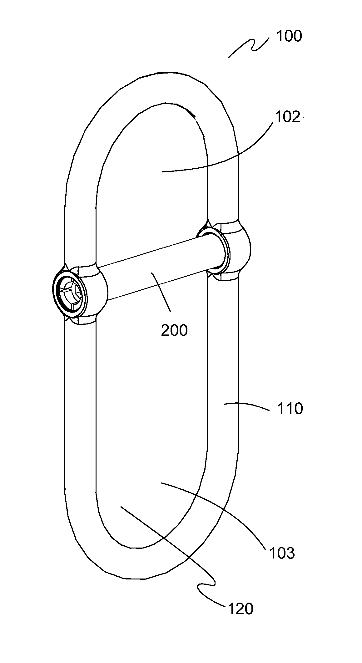
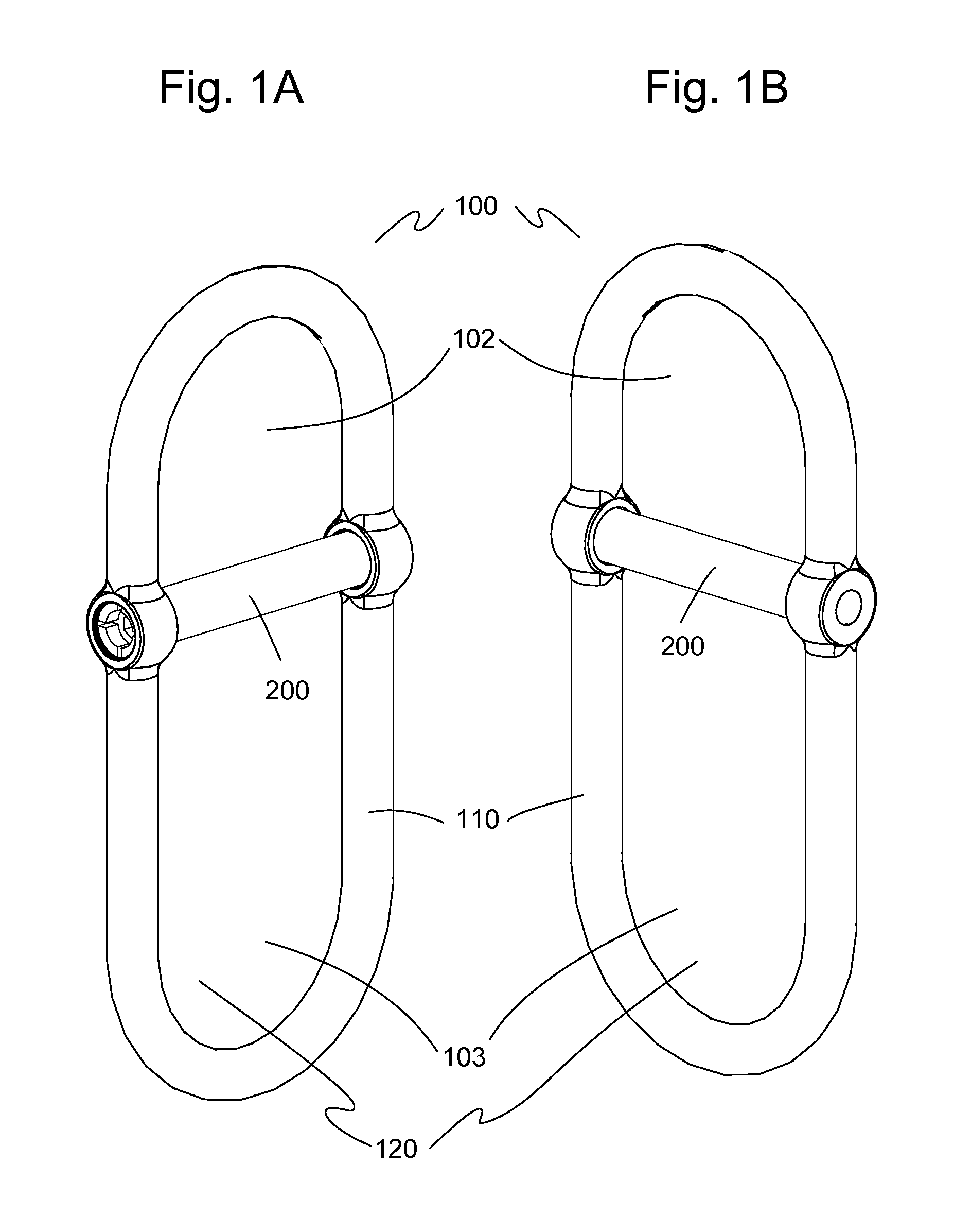
[0078]The preferred embodiments of a shackle assembly 100 of the present invention are illustrated in FIGS. 1-20. FIGS. 1A and 1B illustrate front and rear perspective views, respectively, of one embodiment of a shackle assembly 100 having a body 110 and a pin 200. Body 100 in this embodiment defines a closed oval shape. Pin 110 passes transversely through body 110, dividing a primary opening 120 into two smaller openings 102, 103.

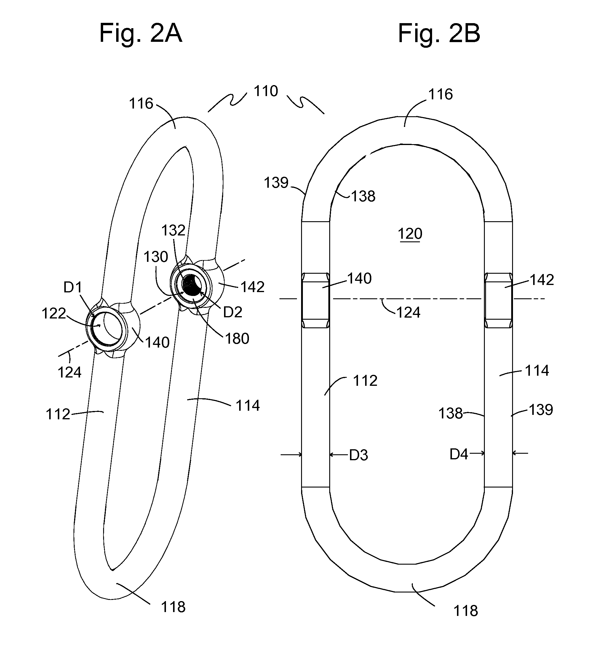
[0079]Referring now to FIGS. 2A and 2B, perspective and front views, respectively, illustrate the embodiment of body 110 as shown in FIG. 1. In one embodiment, body 110 has a longitudinal first side portion 112, a longitudinal second side portion 114 spaced apart from and extending substantially parallel to first side portion 112, a first end portion 116, and a second end portion 118 opposite first end portion 116. Body 110 has an inside body surface 138 and an outside body surface 139. First and second end portions 116, 118 each connect between longitudin...


PUM


Abstract

A combination includes a shackle with a pin and a locking ring. The shackle body has a closed geometry defining a primary opening therethrough and includes a first side member with a first aperture, a second side member spaced apart from the first side member and having a second aperture. The second aperture is positioned opposite from and aligned with the first aperture. End portions extend between and connect the first side member and the second side member. A pin has a body portion extending between a head portion and a tip portion. The pin defines an annular slot extending at least partially around the pin. An expandable retaining ring is configured to be installed on the pin and occupy the annular slot, where the retaining ring prevents removal of the pin from the shackle body when the pin is installed in the shackle body.

Description

BACKGROUND OF THE INVENTION[0001]1. Field of the Invention[0002]The present invention relates locking fasteners and shackle assemblies. More particularly, the present invention relates to a fastener with a locking ring and use of the fastener in a shackle assembly.[0003]2. Description of the Prior Art[0004]Traditionally, a shackle has a U-shaped metal bracket (also known as a clevis) with two arms. The ends of the two arms span an opening between them, which is closed with a bolt or clevis pin inserted through openings in the ends of the arms. Shackles are commonly used to connect multiple items together or secure items to a chain or rope. In some cases, the user loops one end of a strap around the clevis or clevis pin with the other end of the strap being secured to a fixed object. Similar to a bolt, one end of the clevis pin often has an enlarged head or cap that prevents the pin from passing completely through openings in the clevis arms. The opposite end of the clevis pin has a ...

Claims


Application Information

Patent Timeline
IPC IPC(8): F16G15/04
CPCF16G15/06F16C11/045F16G15/04F16G15/08Y10T403/32861
Inventor MOREAU, DARRELL A.MOREAU, ANDRE W.
Owner PURE SAFETY GRP INC
Why Eureka
Try Eureka