
Apparatus and Method for Placing and Mounting Solder Balls on an Integrated Circuit Substrate

Inactive Publication Date: 2015-05-07
ZEN VOCE CORP
View PDF39 Cites 4 Cited by
  • Summary
  • Abstract
  • Description
  • Claims
  • Application Information

AI Technical Summary

Benefits of technology

The invention is about a way to put solder balls on a circuit board that stops multiple balls from being scrapped, which improves production efficiency.

Problems solved by technology

However, a gap between the second fixture and the guiding plate cannot be controlled exactly, so such a conventional method is only applicable for each solder ball with more than 0.25 mm of size, and the plurality of solder balls are scraped easily in a ball placing process.

Method used


Image

  • Apparatus and Method for Placing and Mounting Solder Balls on an Integrated Circuit Substrate
  • Apparatus and Method for Placing and Mounting Solder Balls on an Integrated Circuit Substrate
  • Apparatus and Method for Placing and Mounting Solder Balls on an Integrated Circuit Substrate

Examples


Embodiment Construction

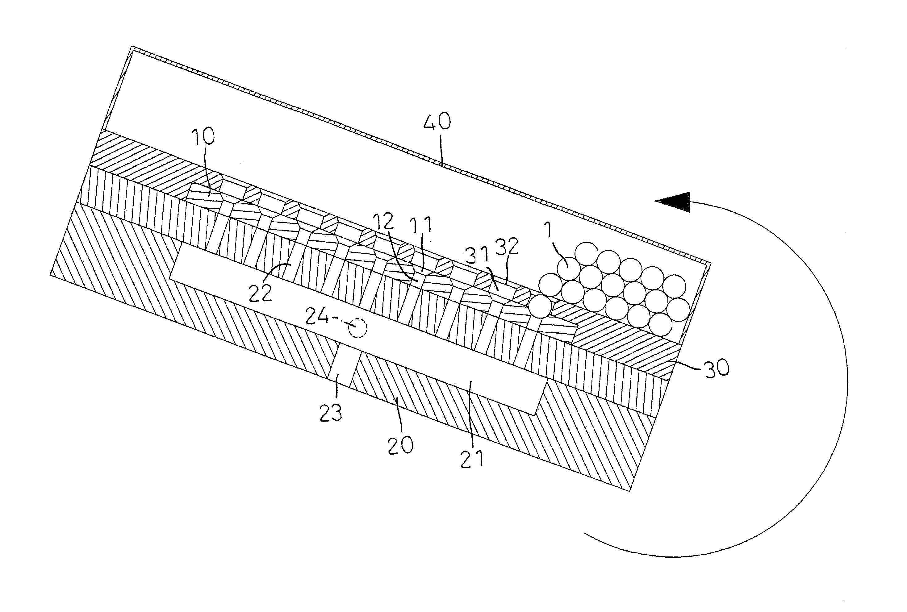
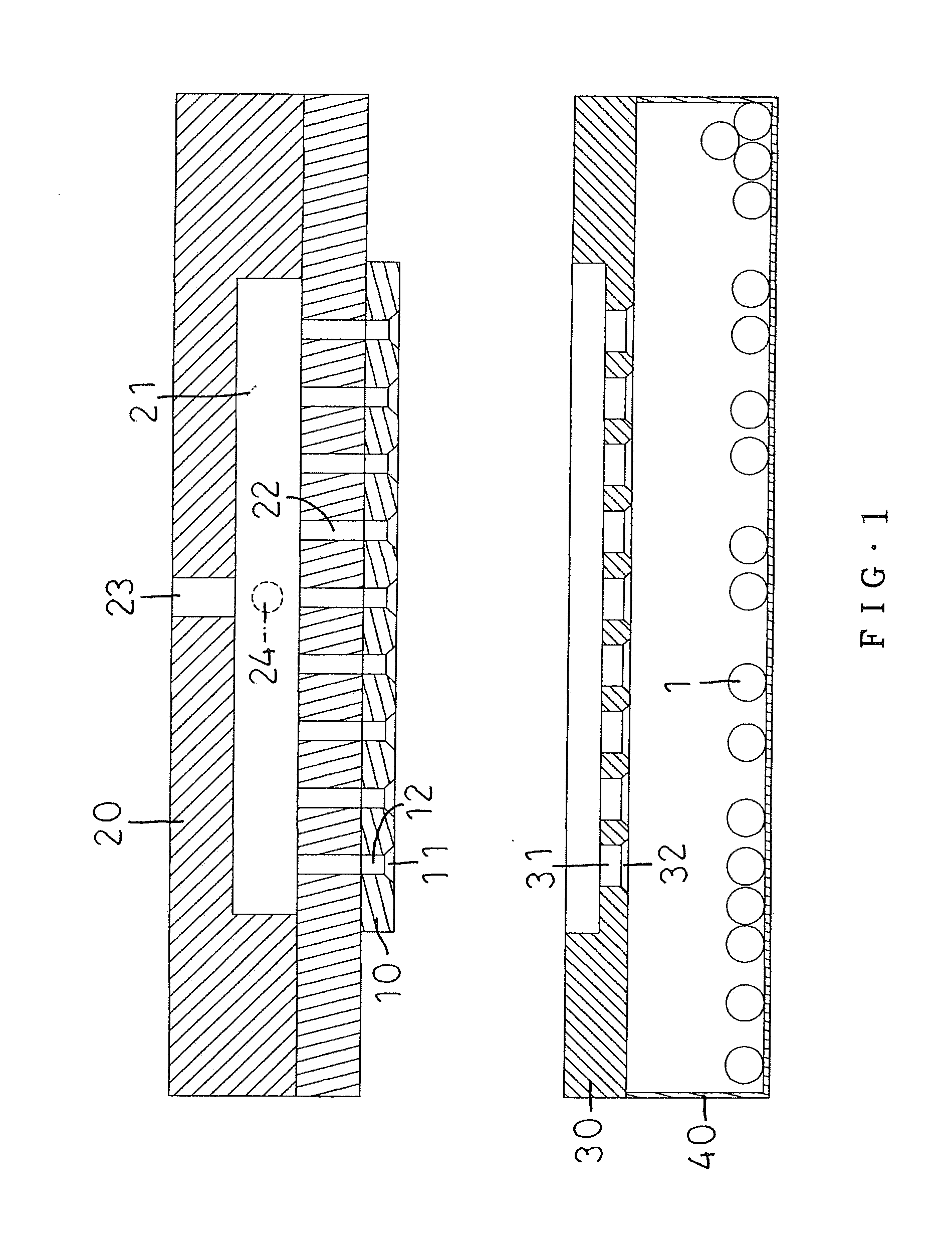
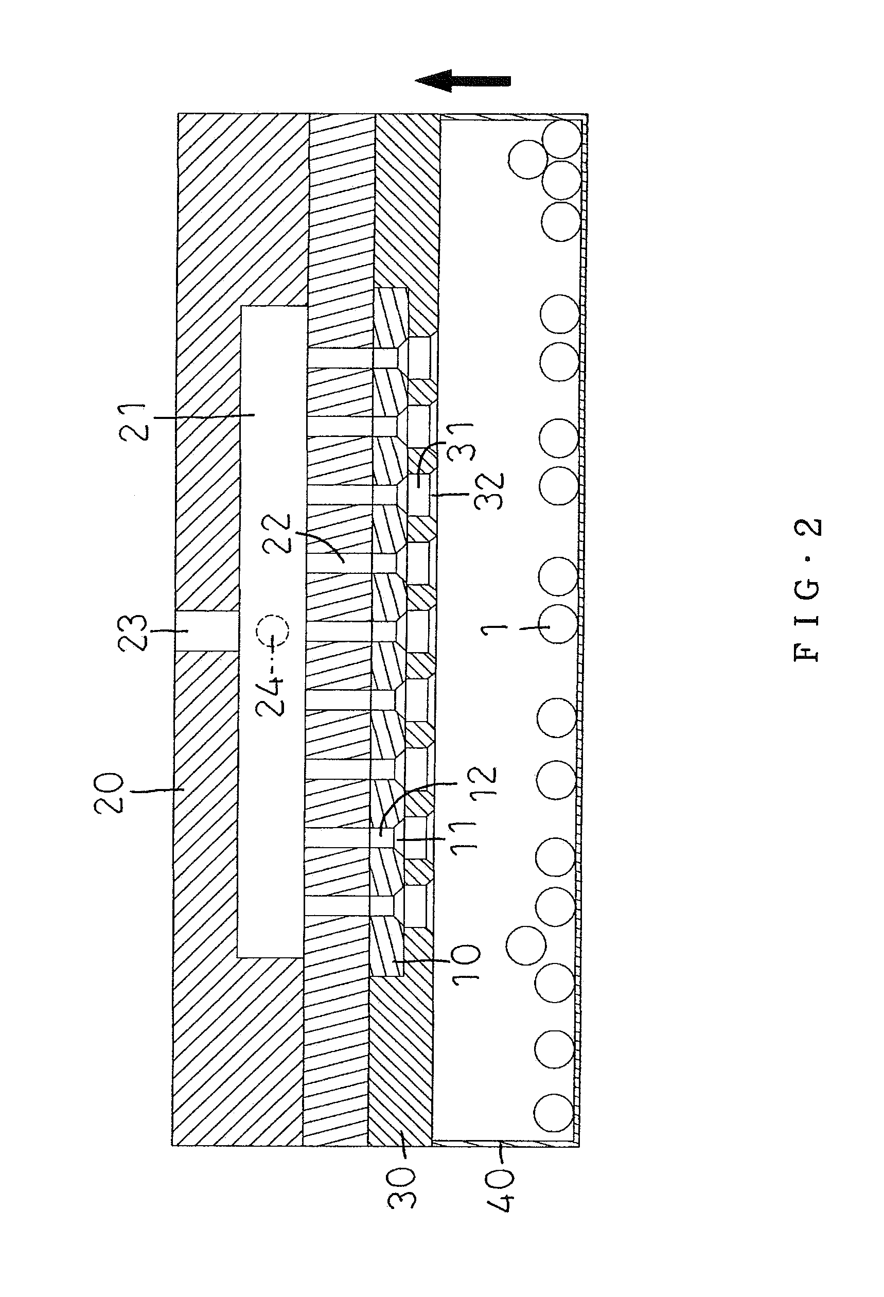
[0038]With reference to FIG. 1, an apparatus for placing and mounting solder balls on an integrated circuit substrate according to a preferred embodiment of the present invention comprises: a fixture 10, a vacuuming device 20, a guiding plate 30, and a storage tank 40.

[0039]The fixture 10 includes a plurality of first grooves 11 defined therein, and each first groove 11 has an upper opening and a lower opening, wherein a diameter of the upper opening is less than that of the lower opening, and each first groove 11 is provided to receive a respective one of a plurality of solder balls 1, and the fixture 10 also includes a plurality of through holes 12 formed therein and located on the plurality of first grooves 11.

[0040]The vacuuming device 20 is disposed over the fixture 10 and includes a vacuum chamber 21 arranged therein and having a plurality of connecting orifices 22 for corresponding to the plurality of through holes 12 of the fixture 10, the vacuum chamber 21 has an air pore 2...


PUM

PropertyMeasurementUnit
Angleaaaaaaaaaa
Diameteraaaaaaaaaa

Abstract

An apparatus for placing and mounting solder balls on an integrated circuit substrate contains: a fixture, a vacuuming device, a guiding plate, and a storage tank. The fixture includes a plurality of first grooves defined therein, the vacuuming device is disposed over the fixture and includes a vacuum chamber which has an air pore so that when air is drawn out of the vacuum chamber via the air pore, a plurality of solder balls are attached, and when the air is fed into the vacuum chamber from the air pore, the plurality of solder balls are released. The guiding plate is secured below the fixture, and the storage tank is arranged below the guiding plate and is applied to accommodate the plurality of solder balls. Thereby, a production yield of placing and mounting the plurality of solder balls on an integrated circuit substrate is enhanced.

Description

FIELD OF THE INVENTION[0001]The present invent relates to an apparatus and a method for placing and mounting solder balls on an integrated circuit substrate which prevent a plurality of solder balls from being scraped so as to enhances production yield.BACKGROUND OF THE INVENTION[0002]A conventional method for mounting solder balls on an integrated circuit substrate contains: a first fixture including a plurality of grooves, and each groove has an upper opening and a lower opening smaller than the upper opening and is served to receive a solder ball. A through hole is defined below a respective one of the plurality of grooves, and a vacuuming device is fixed below the first fixture and includes a vacuuming device formed therein and having a plurality of connecting orifices for corresponding to a plurality of through holes of the first fixture, the vacuuming chamber also has an air pore defined on a central portion thereof so that when air is drawn out of the vacuum chamber via the a...

Claims


Application Information

Patent Timeline
IPC IPC(8): B23K3/06H01L23/00
CPCH01L24/742B23K3/0623B23K1/0016B23K1/203H01L2224/03828H01L24/11H01L2224/11334H01L2224/131B23K2101/42H01L2224/75601H01L2224/75611H01L2224/75621H01L2924/014H01L24/75H01L2224/75102
Inventor LEE, TU-CHEN
Owner ZEN VOCE CORP
Learn More