Coupled torsion beam axle type suspension system

a torsion beam and axle type technology, applied in the direction of interconnection systems, resilient suspensions, vehicle components, etc., can solve the problems of deteriorating turning stability, general instability of movement characteristics of ctba, and deteriorating stability of conventional ctba, so as to secure the overall driving stability of the ctba, reduce the amount of toe-out, and secure the effect of turning stability

Active Publication Date: 2015-05-07
HYUNDAI MOTOR CO LTD
View PDF3 Cites 21 Cited by
  • Summary
  • Abstract
  • Description
  • Claims
  • Application Information

AI Technical Summary

Benefits of technology

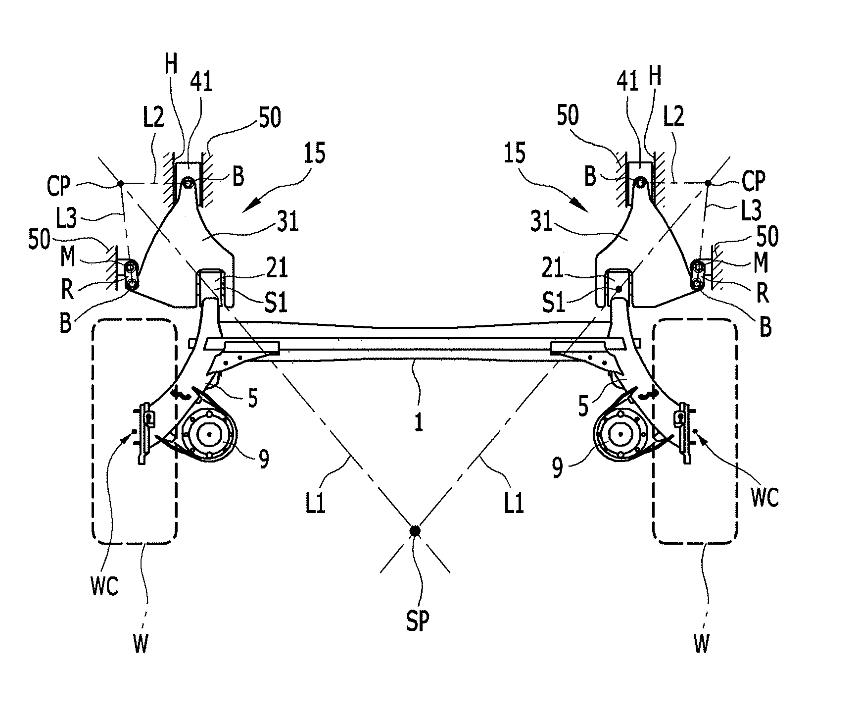
[0039]The exemplary embodiment of the present invention may allow the instantaneous rotational center point of the CTBA to be positioned behind wheel centers by coupling the rotation link coupled to the trailing arm bush to the vehicle body through the slider and the connection link, such that the outer rear wheel is induced to toe-in and the inner rear wheel is induced to toe-out so as to cause the vehicle to be under-steered, thereby securing the turning stability thereof.
[0040]In addition, in a single impact situation when one of the rear-wheels is asymmetrically applied with the thrust and drag forces, such as when driving on a rough road, the instantaneous rotational center point CP of the rotation link with respect to the vehicle body varies and thus the instantaneous rotational center point of the CTBA is moved outside of a line of action where the thrust and drag forces are applied, thereby decreasing the amount of toe-out.
[0041]That is, the amount of rotation of the corresponding rear wheel in a toe-out direction is decreased to secure the overall driving stability of the CTBA.

Problems solved by technology

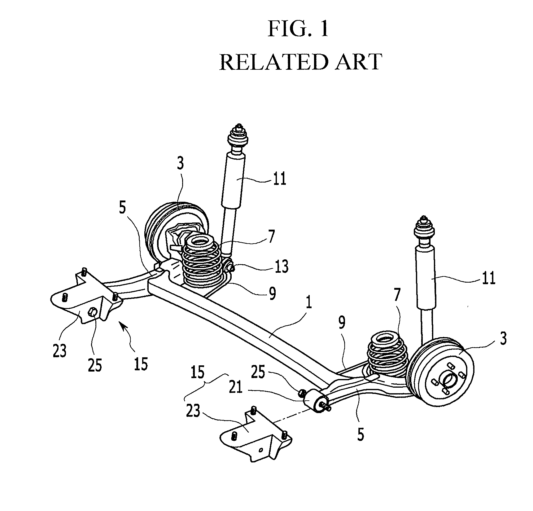
However, the conventional CTBA has following problems in its movement.
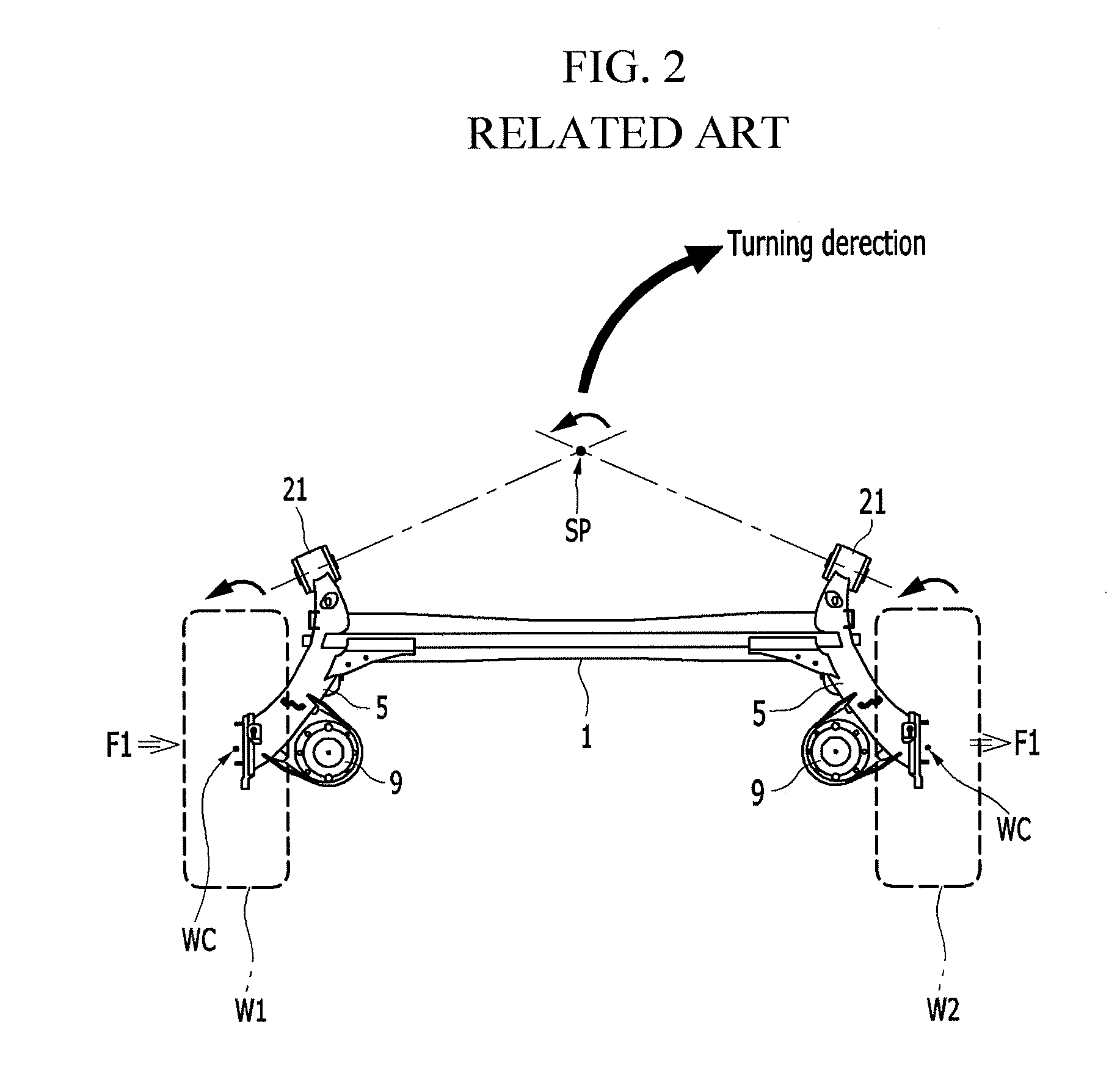
That is, when the vehicle turns, the bumped rear outer wheel W1 is applied with the side force F1 and thus is likely to be induced to toe-out, while the rebounded rear inner wheel W2 is applied with the side force F1 and thus is likely to maintain the previous toe angle or to be induced to toe-in, such that the vehicle is over-steered in general and thus causes deterioration of turning stability.
However, in FIG. 4 C3, in a single impact environment in which one of the rear wheels is asymmetrically applied with the thrust and drag forces F2, the corresponding rear wheel is induced to toe-out which makes the movement characteristics of the CTBA unstable in general, thereby deteriorating the driving stability as in the previous example according to the related art.

Method used


Image

  • Coupled torsion beam axle type suspension system
  • Coupled torsion beam axle type suspension system
  • Coupled torsion beam axle type suspension system

Examples


Embodiment Construction

[0052]Reference will now be made in detail to various embodiments of the present invention(s), examples of which are illustrated in the accompanying drawings and described below. While the invention(s) will be described in conjunction with exemplary embodiments, it will be understood that the present description is not intended to limit the invention(s) to those exemplary embodiments. On the contrary, the invention(s) is / are intended to cover not only the exemplary embodiments, but also various alternatives, modifications, equivalents and other embodiments, which may be included within the spirit and scope of the invention as defined by the appended claims.

[0053]Hereinafter, an exemplary embodiment of the present invention will be described in detail with reference to the accompanying drawings.

[0054]However, the size and thickness of each component illustrated in the drawings are arbitrarily shown for ease of description and the present invention is not limited thereto, and the thic...


PUM


Abstract

A coupled torsion beam axle type suspension system (CTBA) may include trailing arms respectively coupled to opposite ends of a torsion beam, and a vehicle body-engaging unit provided in a front end portion of each of the trailing arm and engaging the each of the trailing arms to a vehicle body, wherein each vehicle body-engaging unit includes a trailing arm bush that may be coupled to a front end portion of the trailing arm, a rotation link disposed in front of the trailing arm bush and engaged thereto in a width direction of a vehicle, a slider rotatably connected to a front end portion of the rotation link, and slidable along a length direction of the vehicle body, and a connection link pivotally connecting an outer end portion of the rotation link and the vehicle body.

Description

CROSS-REFERENCE TO RELATED APPLICATION[0001]The present application claims priority to and the benefit of Korean Patent Application No. 10-2013-0132958 filed on Nov. 4, 2013, the entire contents of which is incorporated herein for all purposes by this reference.BACKGROUND OF THE INVENTION[0002]1. Field of the Invention[0003]The present invention relates to a coupled torsion beam axle type suspension system, and more particularly, to a coupled torsion beam axle type suspension system for improving single impact characteristics of an outer rear wheel with respect to thrust and drag forces as well as controlling movement (i.e., toe) characteristics thereof with respect to a side force, when a vehicle turns.[0004]2. Description of Related Art[0005]Generally, despite a limitation in design performance factors such as ride comfort, driving stability, etc., a coupled torsion beam axle type suspension system (hereinafter referred to as a CTBA) has been primarily applied to rear wheel suspen...

Claims


Application Information

Patent Timeline
Patent Type & Authority Applications(United States)
IPC IPC(8): B60G21/05
CPCB60G21/052B60G2200/21B60G2200/34B60G2200/462B60G2204/1434B60G2204/4106B60G2204/421B60G2204/422B60G11/18B60G7/02B60G7/04B60G11/12
Inventor LEE, JAEKILKIM, SEON PYUNGCHO, YOUN HYUNGJUNG, JIN-HOJEONG, SEONG HEE
Owner HYUNDAI MOTOR CO LTD
Why Eureka
Try Eureka