40g/100g/200g/400g pluggable optical transceivers with advanced functionality

a technology of pluggable optical transceivers and advanced functionality, which is applied in the field of optical and data networking, can solve problems such as limiting the performance of optical transceivers, and achieve the effect of transparent circuitry operation and preservation of backward compatibility for operation

Active Publication Date: 2015-05-07
LUMENTUM OPERATIONS LLC
View PDF5 Cites 38 Cited by
  • Summary
  • Abstract
  • Description
  • Claims
  • Application Information

AI Technical Summary

Benefits of technology

[0007]In another exemplary embodiment, a multi-source agreement (MSA) compliant optical transceiver includes an optical section including transmit optics and receive optics; an electrical section communicatively coupled to the optical section; circuitry in the electrical section configured to provide framing and forward error correction integrated within the MSA compliant optical transceiver and transparent to a host system housing the MSA compliant optical transceiver, wherein the host system is supports optical transceivers compliant to the MSA; a controller communicatively coupled to the optical section, the electrical section, and the host system; a housing compliant to the MSA, the housing containing the optical section, the electrical section, and the controller; and a communications port disposed on the housing and communicatively coupled to the controller, wherein the communications port is utilized to monitor and control operations, administration, maintenance, and provisioning (OAM&P) data associated with the circuitry thereby enabling a transparent manner of operation of the circuitry with respect to the host device.
[0008]In an exemplary embodiment, a pluggable optical transceiver configured to operate in a host device includes a communication link configured to interface with the host device for providing a high-speed signal therebetween; framing and forward error correction circuitry configured to provide framing and forward error correction related to the high-speed signal; transmitter optical components communicatively coupled to the framing and forward error correction circuitry and configured to transmit a composite optical output signal; and receiver optical components communicatively coupled to the circuitry and configured to receive a composite optical input signal; wherein the framing and forward error correction is performed within the pluggable optical transceiver separately and independently from the host device. The communication link can have N signaling lanes each at M Gb/s, and the high-speed signal is at least 40 Gb/s such that N×M is at least 40 Gb/s. The pluggable optical transceiver can further include a controller in the pluggable optical transceiver communicatively coupled to the framing and forward error correction circuitry and the host device, wherein the controller is configured to one of terminate operations, administration, maintenance, and provisioning (OAM&P) data in the pluggable optical transceiver independent of the host device, provide full access to the OAM&P data at the host device or provide reduced access to the OAM&P data at the host device.
[0009]The transmitter optical components can include a multiplexer section and a transmitter optics section and the receiver optical components comprise a demultiplexer section and a receiver optics section; wherein the multiplexer section is coupled to the framing and forward error correction circuitry through X signaling lanes and coupled to the transmitter optics section through Y signaling lanes; and wherein the receiver optics section is coupled to the demultiplexer section through Y signaling lanes and the demulti

Problems solved by technology

Advantageously, this enables interoperability among equipment vendors of optical transceivers, i.e. any MSA-compatible optical transceiver can be used in any host system designed to the MSA specification; however, these tightly d

Method used


Image

  • 40g/100g/200g/400g pluggable optical transceivers with advanced functionality
  • 40g/100g/200g/400g pluggable optical transceivers with advanced functionality
  • 40g/100g/200g/400g pluggable optical transceivers with advanced functionality

Examples


Embodiment Construction

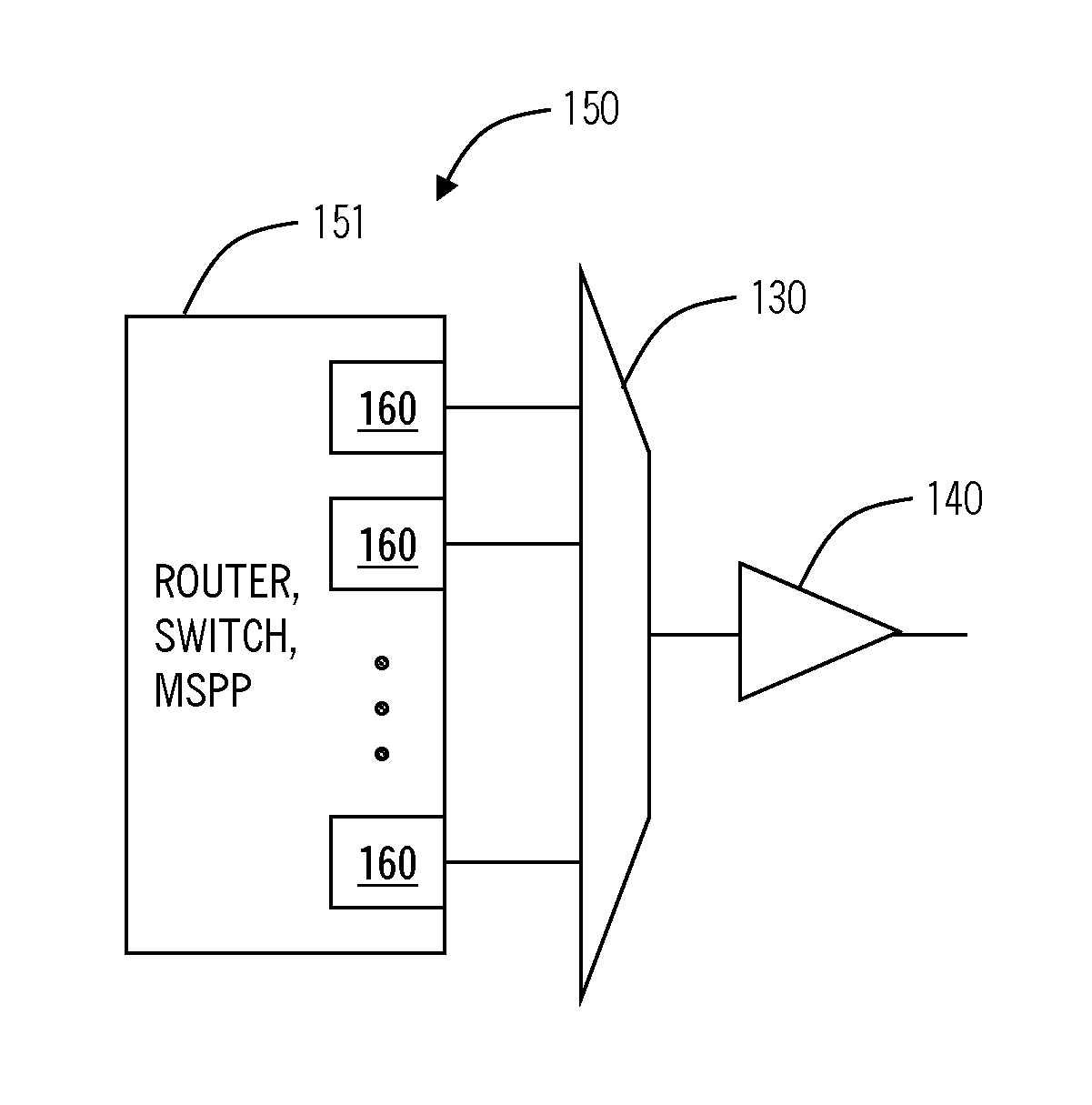
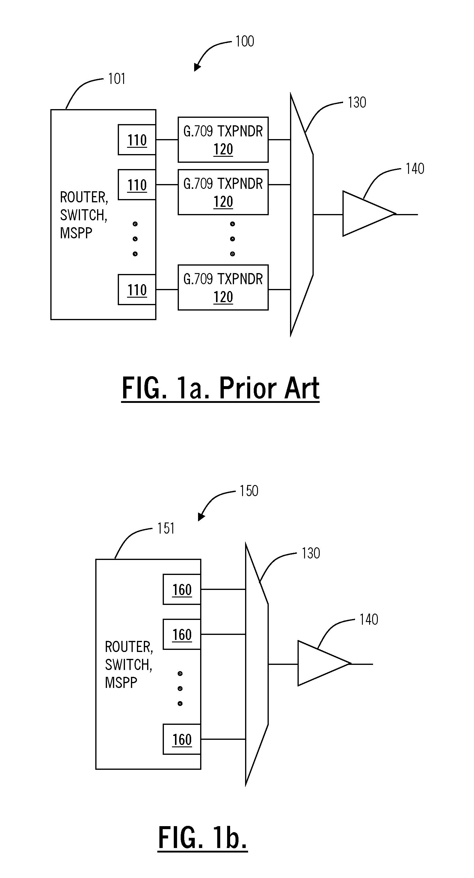
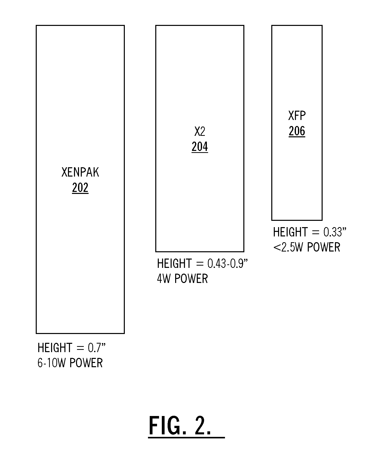
[0051]In various exemplary embodiments, the present disclosure provides integrated performance monitoring (PM); optical layer operations, administration, maintenance, and provisioning (OAM&P); alarming; and other advanced functionality in optical transceivers, such as multi-source agreement (MSA)-defined modules. The present disclosure provides an optical transceiver defined by an MSA agreement with integrated PM and alarming for carrier-grade operation. The integration preserves the existing MSA specifications allowing the optical transceiver to operate with any compliant MSA host device. Further, the host device can be configured through software to retrieve the PM and alarming from the optical transceiver. The optical transceiver can include CFP and variants thereof (e.g., CFP2, CFP4, CXP), CDFP and variants thereof (e.g., CDFP2, CDFP4, etc.), MSA-100GLH, CCRx, QSFP and variants thereof (e.g., future QSFP+, QSFP2), 10×10, XFP, XPAK, XENPAK, X2, XFP-E, SFP, SFP+, 300-pin, and the ...


PUM


Abstract

Integrated performance monitoring (PM); optical layer operations, administration, maintenance, and provisioning (OAM&P); alarming; amplification, and the like is described in optical transceivers, such as multi-source agreement (MSA)-defined modules. A pluggable optical transceiver defined by an MSA agreement can include advanced integrated functions for carrier-grade operation which preserves the existing MSA specifications allowing the pluggable optical transceiver to operate with any compliant MSA host device with advanced features and functionality, such as Forward Error Correction (FEC), framing, and OAM&P directly on the pluggable optical transceiver. The advanced integrated can be implemented by the pluggable optical transceiver separate and independent from the host device.

Description

CROSS-REFERENCE TO RELATED APPLICATION(S)[0001]This application is a continuation-in-part of co-pending U.S. patent application Ser. No. 13 / 784,998 filed Mar. 5, 2013, and entitled “40 G / 100 G MSA-COMPLIANT OPTICAL TRANSCEIVERS WITH ADVANCED FUNCTIONALITY,” which claims priority as a continuation-in-part of U.S. Pat. No. 8,412,051, issued on Apr. 2, 2013, and entitled “40 G / 100 G OPTICAL TRANSCEIVERS WITH INTEGRATED FRAMING AND FORWARD ERROR CORRECTION,” which claims priority to U.S. Pat. No. 8,107,820 issued Jan. 31, 2012, and entitled “SYSTEMS AND METHODS FOR THE INTEGRATION OF FRAMING, OAM&P, AND FORWARD ERROR CORRECTION IN SFP OPTICAL TRANSCEIVER DEVICES,” which claims priority to U.S. Provisional Pat. Appl. No. 61 / 029,821, filed Feb. 19, 2008, and entitled “SYSTEMS AND METHODS FOR ETHERNET EXTENSION AND DEMARCATION,” and which claims priority as a continuation-in-part of U.S. Pat. No. 7,580,637, issued on Aug. 25, 2009, and entitled “SYSTEMS AND METHODS FOR THE INTEGRATION OF F...

Claims


Application Information

Patent Timeline
IPC IPC(8): H04B10/40
CPCH04B10/40H04J3/047H04L1/0057H04J2203/006H04J2203/0085H04L1/0041H04L1/004G02B6/4284G02B6/4292H04B10/25133H04B10/2569H04J3/1652H04J14/08H04L1/0042H03M13/1515H04B10/6162H04L1/0045H04L1/0058H04L7/0075
Inventor EL-AHMADI, SIRAJ NOUREL AHMADI, SALAMHOTCHKISS, ADAM R.CARDONA, GABRIEL E.
Owner LUMENTUM OPERATIONS LLC
Why Eureka
Try Eureka