Minimally invasive spinal facet compression screw and system for bone joint fusion and fixation

a compression screw and minimally invasive technology, applied in the field of implants, can solve the problems of limited effectiveness, lack of provisions for incorporating fusion components, and little mechanical fixation of facet joints, and achieve the effect of preventing the screw from loosening and preventing the disengagement of the screw driver locking sleev

Active Publication Date: 2015-05-07
X SPINE SYST
View PDF5 Cites 0 Cited by
  • Summary
  • Abstract
  • Description
  • Claims
  • Application Information

AI Technical Summary

Benefits of technology

This patent describes a screw implant with bone-locking features that help prevent the screw from loosening. The implant also has a screw driver attachment zone with additional threads to prevent the screw driver locking sleeve from disengaging. The implant also includes a locking slot or aperture to facilitate bone growth into the implant. The patent also provides a method for fixing bones together using the screw implant and biological material. Additionally, the patent describes an anti-rotation device to prevent the screw from rotating after insertion into the patient.

Problems solved by technology

This has limited effectiveness due to the limited ability of the relatively fragile facet joint to withstand external screw-tightening forces.
A disadvantage to prior art facet screw systems is that while they address the potential for percutaneous placement of the screw (fixation) component, none have provisions to incorporate the fusion component in this manner.
Although these systems address the fusion component, they confer little, if any, mechanical fixation of the facet joint.
This defeats a major advantage of facet screw placement, i.e. a simple, minimally-invasive approach.
This also limits the procedure to traditional operating room settings where larger procedures can be supported.
Such screws, however, are not designed to incorporate a fusion mass across two adjacent facet joints wherein the screw itself comprises both a fixation component and fusion component.

Method used


Image

  • Minimally invasive spinal facet compression screw and system for bone joint fusion and fixation
  • Minimally invasive spinal facet compression screw and system for bone joint fusion and fixation
  • Minimally invasive spinal facet compression screw and system for bone joint fusion and fixation

Examples


Embodiment Construction

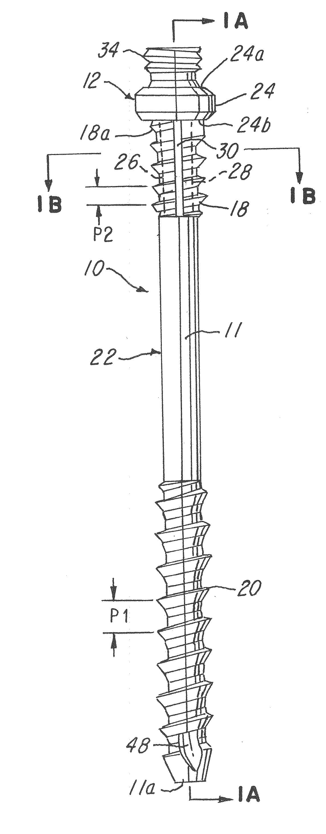
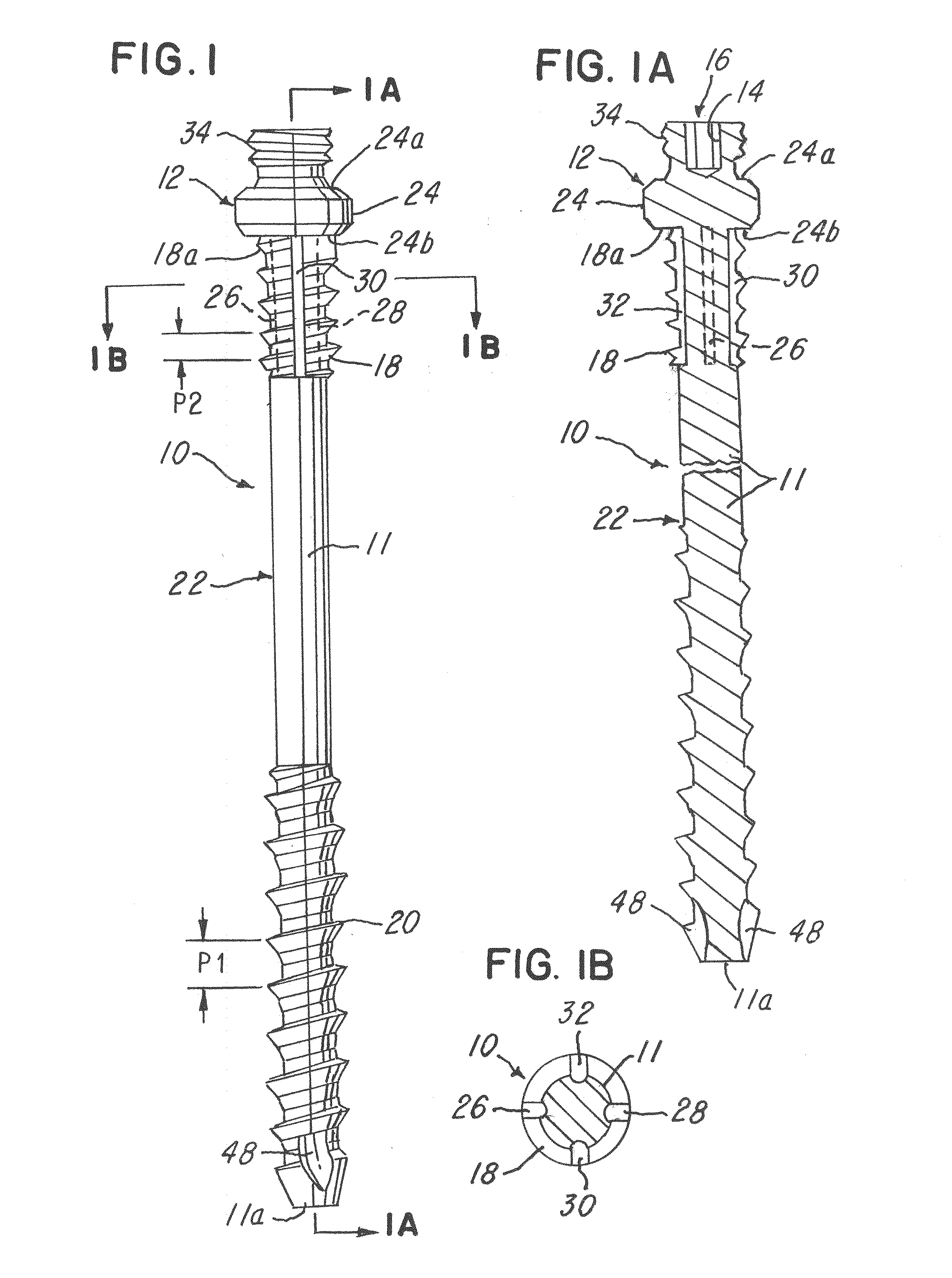
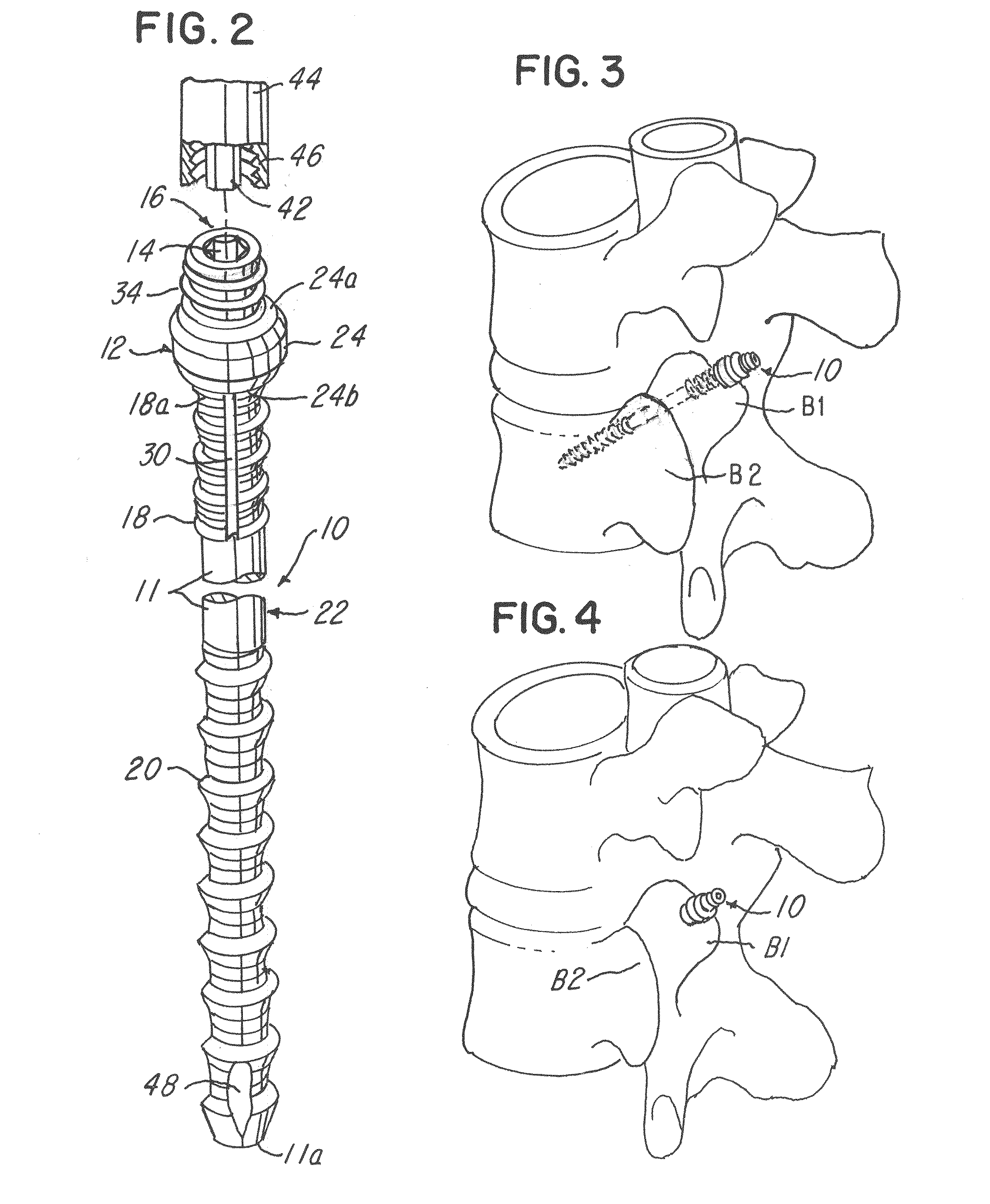
[0116]Referring now to FIGS. 1-5D, a surgical implant 10 is shown. In the embodiment being described, the surgical implant 10 comprises a body 11. The body 11 comprises a screw head 12 having an aperture or tool attachment zone 16. In the illustration, the tool attachment zone 16 comprises an internal wall 14 that defines the aperture or tool attachment zone 16 (FIG. 1A) in the form of a tool receiving aperture for receiving a screw driver 40 (FIG. 2).

[0117]The surgical implant 10 further comprises a proximal or first thread 18, a distal or second thread 20 and an intermediate portion 22 that is not threaded and that is integral or monolithically formed with the first thread 18 and second thread 20 as shown. In the illustration being described, it should be understood that pitch distances of each of the first threads 18 and second threads 20 are different. Thus, note in FIG. 1 that a pitch distance P1 for the distal or second threads 20 is larger than a pitch distance P2 of the prox...


PUM


Abstract

A system comprising a screw element having a generally cylindrical body having a bore or lumen therethrough and a plurality of fenestrations or windows through which biological material may be provided. The system comprises a tool for inserting the biological material into the screw element so that the biological material may extrude through the plurality of fenestrations or windows and through an aperture in the tip of the screw element thereby enabling providing a fusion mass across two adjacent facet bones or a facet joint wherein the screw itself provides both a fixation component and a screw component.

Description

CROSS-REFERENCE TO RELATED APPLICATION[0001]This application is a continuation of U.S. patent application Ser. No. 13 / 413,021 filed Mar. 6, 2012, which is a continuation-in-part of U.S. patent application Ser. No. 13 / 184,862 filed Jul. 18, 2011, which claims priority to U.S. Provisional Patent Application No. 61 / 365,906 filed Jul. 20, 2010, to which Applicant claims the benefit of the earlier filing dates and which applications are incorporated herein by reference in their entirety and made a part hereof.BACKGROUND OF THE INVENTION[0002]1. Field of the Invention[0003]This invention relates to implants, and more particularly, to a spinal facet compression screw comprising a plurality of variable pitch thread zones and a buttress head. Another embodiment relates to a minimally invasive spinal facet joint fusion and fixation system.[0004]2. Description of the Related Art[0005]The field of spinal implantation burgeons with devices and methods for the achievement of fixation between adja...

Claims


Application Information

Patent Timeline
Patent Type & Authority Applications(United States)
IPC IPC(8): A61B17/70
CPCA61B17/7098A61B17/7082A61B17/7064A61B17/861A61B17/863A61B17/864A61B17/8841A61B17/8891
Inventor KIRSCHMAN, DAVID LOUIS
Owner X SPINE SYST
Why Eureka
Try Eureka