System and method for modular robotic system

a robotic system and modular technology, applied in the field of modular robotic systems, can solve the problems of inconvenient customization, inconvenient operation, and inefficient cable arrangement, and achieve the effect of simple touch and drag user interface and easy customization of operation and function

Inactive Publication Date: 2015-05-07
THE TECH MUSEUM OF INNOVATION
View PDF5 Cites 17 Cited by
  • Summary
  • Abstract
  • Description
  • Claims
  • Application Information

AI Technical Summary

Benefits of technology

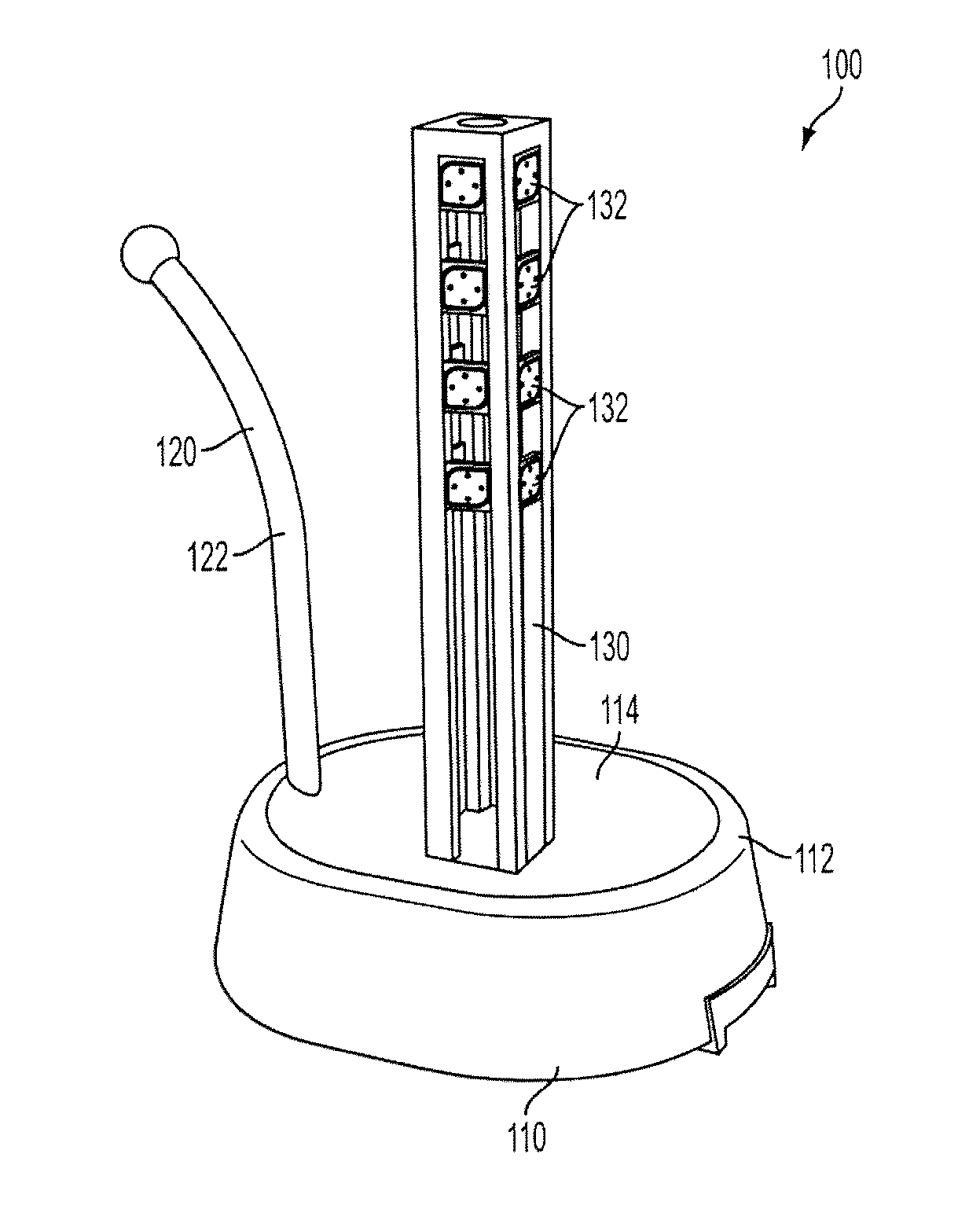
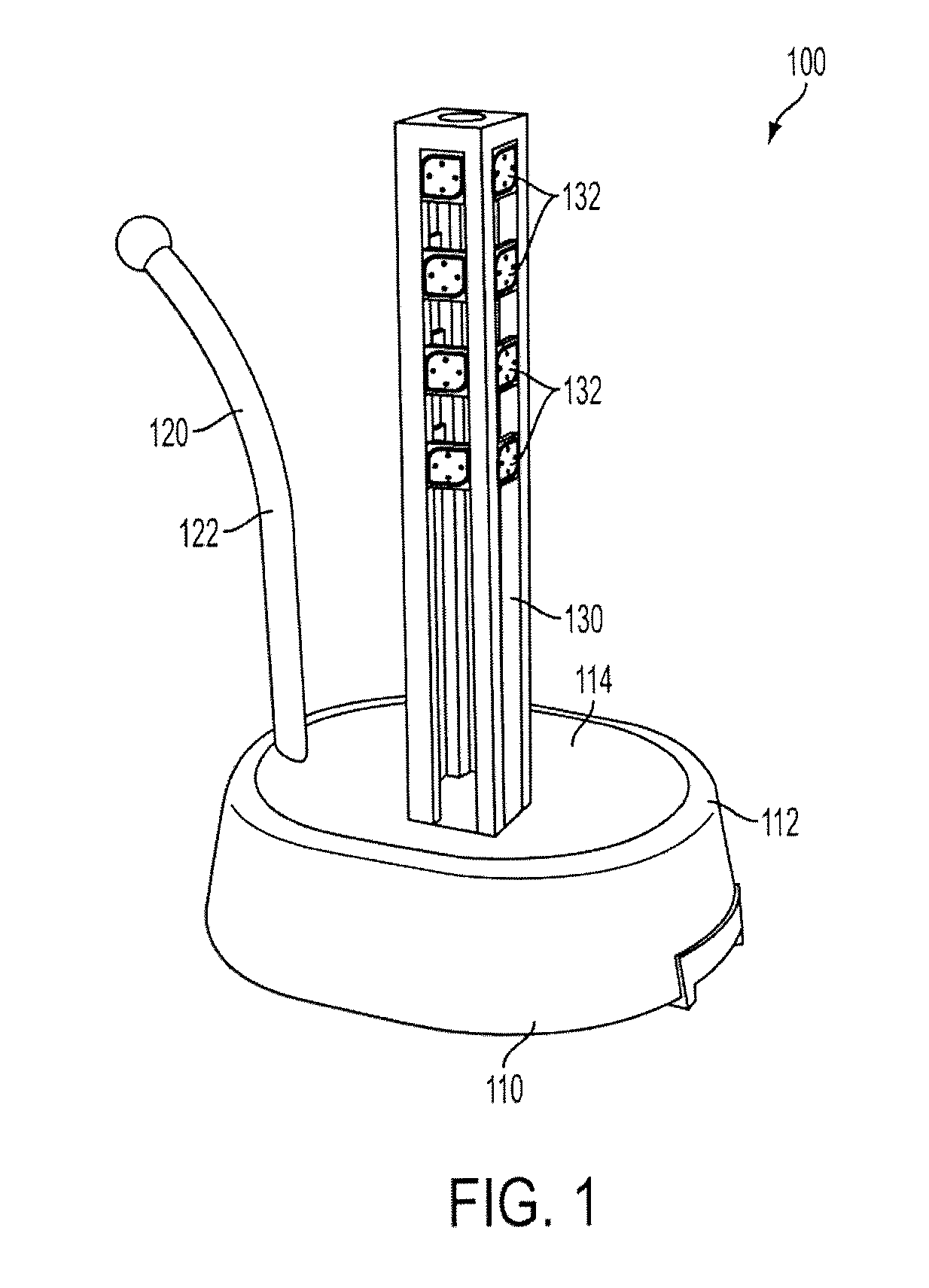
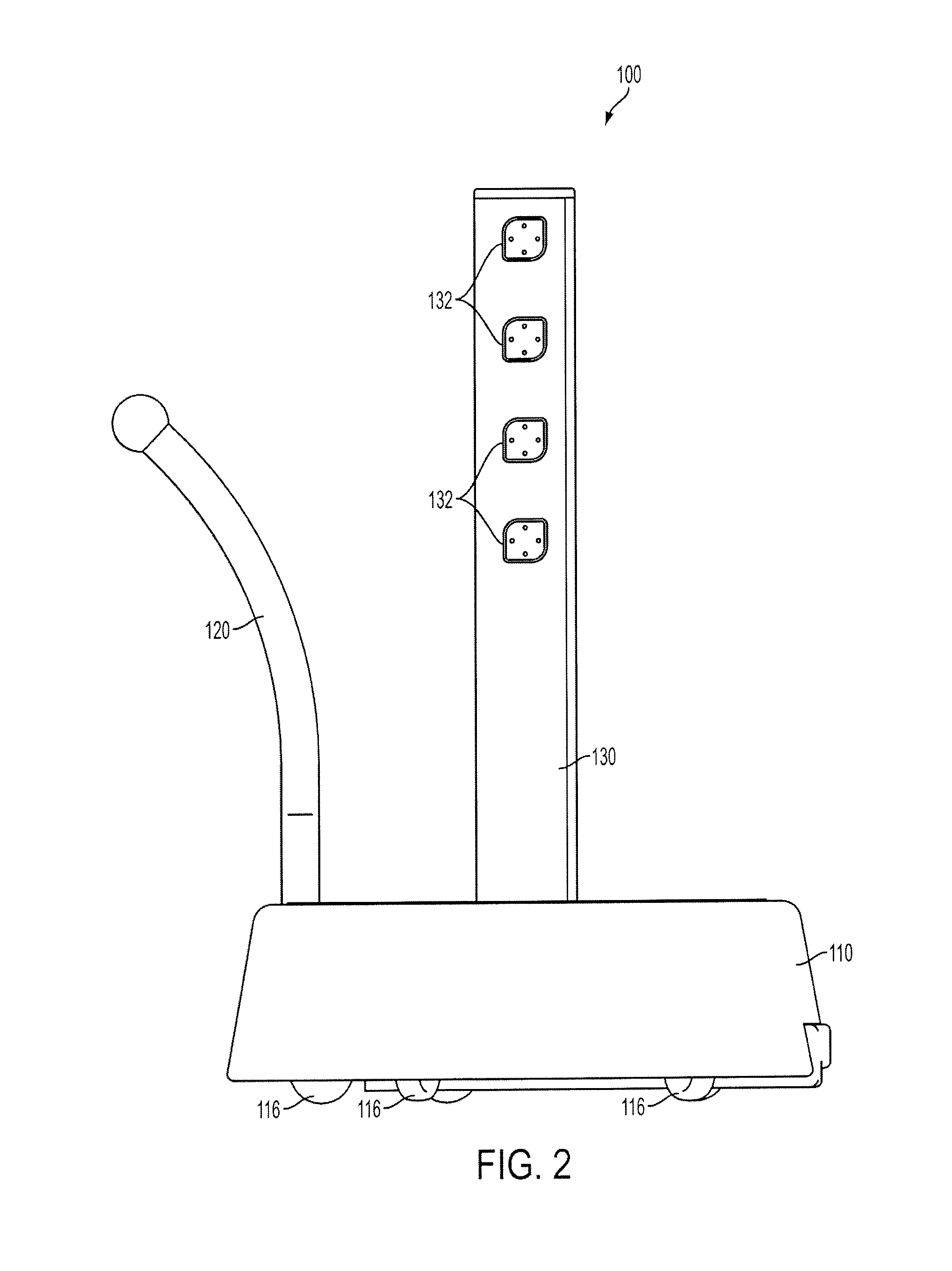
[0008]The modular robotic system and method contemplated herein includes a robot base unit that has a battery housing containing a power source and a magnetic tower connected to the battery housing that includes a plurality of magnetic sockets. The method and system further includes modular components that each include magnetic coupling members attachable to the magnetic sockets, such that the connected modular components receive power from the battery of the base unit. The modular components further include a connection port for data communication with a connected modular component and a processor that can transmit status and query data to the connected modular component. In addition, system and method include a programming station that can be patched to a particular robot that enables a user to easily customize the operation and function of the components of the patched robot using a simple touch and drag user interface.

Problems solved by technology

This design makes the cable arrangement extremely cumbersome and inefficient when dealing with many multi-conductor cables between multiple robot modules.
Moreover, while the user can establish certain functional relationships between the component based on the specific connection between the components, the customization is very limited and generally provides a simple input to output linear response.

Method used


Image

  • System and method for modular robotic system
  • System and method for modular robotic system
  • System and method for modular robotic system

Examples


Embodiment Construction

[0030]A system and method for a customizable robotic system is disclosed herein. Each of the features and teachings disclosed herein can be utilized separately or in conjunction with other features and teachings. Representative examples utilizing many of these additional features and teachings, both separately and in combination, are described in further detail with reference to the attached drawings. This detailed description is merely intended to teach a person of skill in the art further details for practicing preferred aspects of the present teachings and is not intended to limit the scope of the claims. Therefore, combinations of features disclosed in the following detailed description may not be necessary to practice the teachings in the broadest sense, and are instead taught merely to describe particularly representative examples of the present teachings.

[0031]In the following description, for purposes of explanation only, specific nomenclature is set forth to provide a thoro...


PUM


Abstract

A user-customizable modular robotic method and system that includes a robot base unit that has a battery housing containing a power source and a magnetic tower connected to the battery housing that includes a plurality of magnetic sockets. The method and system further includes modular components that each include magnetic coupling members attachable to the magnetic sockets, such that the connected modular components receive power from the battery of the base unit. The modular components further include a connection port for data communication with a connected modular component and a processor that can transmit status and query data to the connected modular component. In addition, system and method include a programming station that can be patched to a particular robot that enables a user to easily customize the operation and function of the components of the patched robot using a simple touch and drag user interface.

Description

CROSS REFERENCE TO RELATED APPLICATIONS[0001]This application claims the benefit of U.S. Provisional Application No. 61 / 839,782, filed on Jun. 26, 2013, the entire contents of which are hereby incorporated by reference.BACKGROUND[0002]1. Field[0003]The present patent document relates generally to a system and method for a robotic system, and, more particularly, to a modular robotic system and method with user-customized operational control.[0004]2. Description of the Related Art[0005]A variety of robotic systems are known in the art particularly for use in automated performance of various manufacturing processes, household chores, toys and the like. Conventional robotic mechanisms typically comprise an assembly of mechanical components some of which can be added and removed to provide a user with a certain level of operational customization of the robot.[0006]Historically, the robots can be customized by connection certain components of the robot to each other, for example, connecti...

Claims


Application Information

Patent Timeline
Patent Type & Authority Applications(United States)
IPC IPC(8): B25J9/08
CPCB25J9/08B25J5/007B25J13/06B25J19/005B25J9/1617
Inventor CARLSON, LATH B.SO, EMIL C.STREELMAN, DANIEL A.
Owner THE TECH MUSEUM OF INNOVATION
Why Eureka
Try Eureka