
Spinner fishing lure

a technology of spinning lures and lures, which is applied in the field of fishing lures, can solve the problems of preventing the lure from working properly, presenting another vexing problem, and a disadvantage of spinning lures,

Inactive Publication Date: 2015-05-14
HEESCH CHRISTIAN M
View PDF19 Cites 8 Cited by
  • Summary
  • Abstract
  • Description
  • Claims
  • Application Information

AI Technical Summary

Benefits of technology

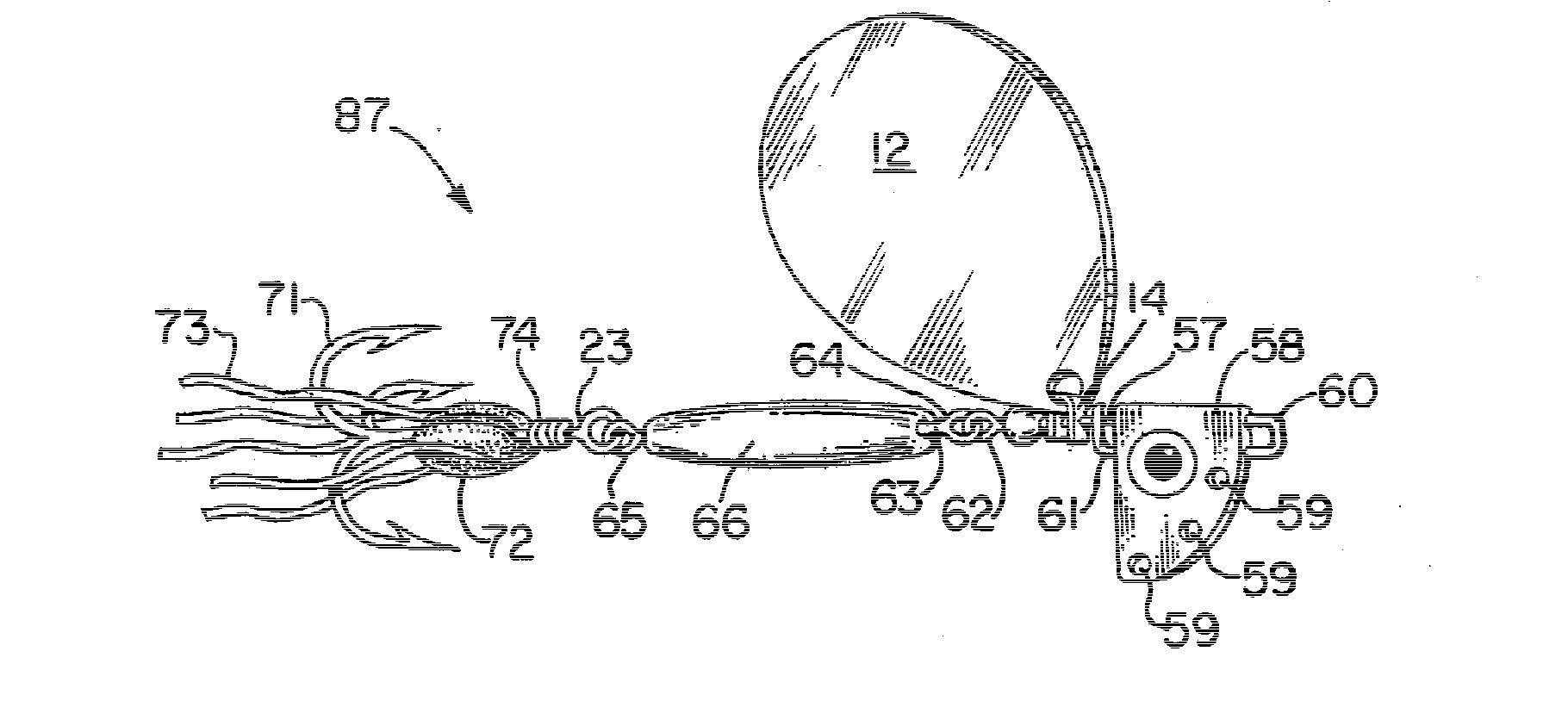
This patent is about a new type of fishing lure that has a rotating blade attached to a stiff wire shaft. Unlike traditional spinners, the stiff wire shaft ends right below the attachment site of the spinning blade. This lure is shorter and has a flexible wire or split ring element forming its distal long axis portion, which may carry one or more lure body elements that are not heavily weighted. The front portion of this lure can be used separately, by linking it to existing lures, to increase the fish catching potential of previously unsuccessful lures.

Problems solved by technology

This advantage of spinner baits is a disadvantage at the same time, though, since the enhanced attractiveness of the blade-carrying arm of the spinner bait detracts the fish's attention from the object intended for its affection—the hook-carrying opposite arm of the lure.
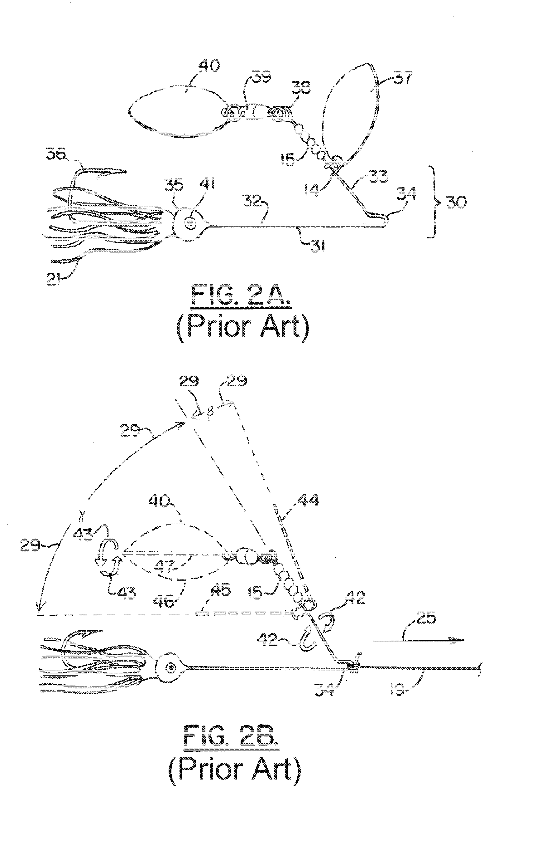
Spinners, with a weighted lure body in the middle of the lure, and often bulky but light-weight dressing around a treble hook at the end, are notorious for the hook fowling the line during the casting process, subsequently preventing the lure from working properly when in the water.
Further, due to the rapid rotation of the blade around the axis of the lure, spinners often present another vexing problem: line twist.
The rotating blade imparts a rotating movement on the spinner itself, which is transmitted onto the fishing line, causing its eventual entanglement and damage.
Lastly, all artificial lures, as opposed to natural baits, pose yet another problem to the fisherman: fish tend to come off after striking the lure by ‘throwing the hook’.
Twisting and turning movements of the fish, and shaking of its head, will often lead to dislodgement of the hook and loss of the fish, with the lure serving as a lever.

Method used


Image

  • Spinner fishing lure
  • Spinner fishing lure
  • Spinner fishing lure

Examples


Embodiment Construction

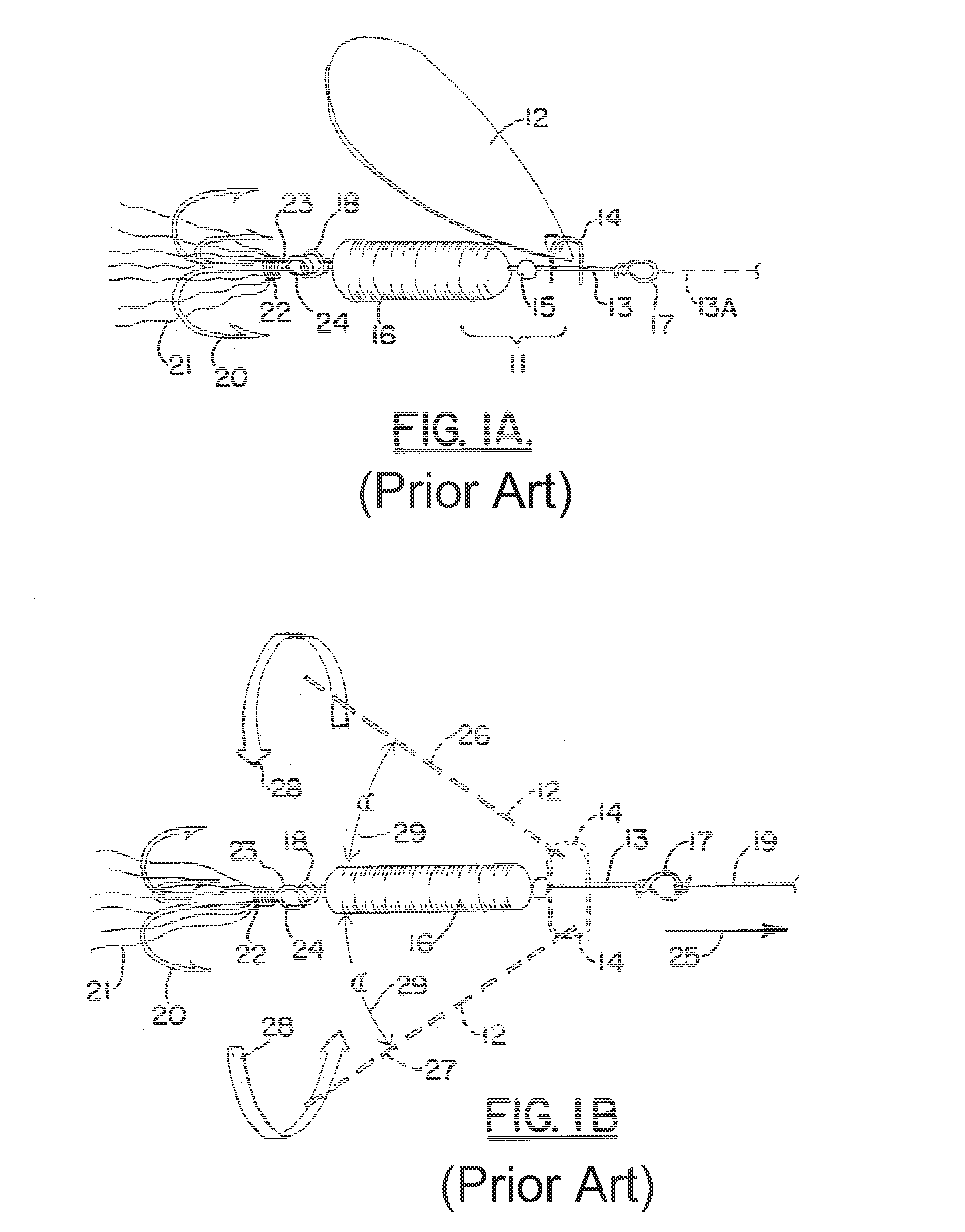
[0045]FIG. 1A shows a traditional spinner 11. A rotating blade 12 is mounted on a single wire shaft 13 by a clevis 14. Below clevis 14, a small metal or plastic bead 15, also mounted on wire axis 13, facilitates the rotational movements of clevis 14 and blade 12 around axis 13. Below bead 15, one or more lure body components 16 provide weight to allow for better casting of the lure. At the proximal and distal ends of single wire shaft 13, proximal wire shaft eye 17 and distal wire shaft eye 18 allow for the attachment of fishing line 19 (proximally) and of a treble hook 20 (distally). Most spinners also feature decorative dressing material 21 (often consisting of colored animal hair such as buck-tail material), attached with yarn 22 to hook shank 23 below hook eye 24.

[0046]FIG. 1B shows traditional spinner 11 in motion. Fishing line 19 is attached to proximal wire shaft eye 17, and spinner 11 is pulled through the water (not depicted) in a direction generally coaxial to fishing line...


PUM


Abstract

A fishing lure having a long axis provided at its proximal portion, an elongated stiff wire shaft having a bent or looped portion on its proximal end for attaching fishing line or a swivel thereto, and a bent or looped portion on its distal end. The distal portion of said long axis is formed by either a flexible element, or by a second elongated stiff wire shaft, or by one or more split rings. At the distal end one or more hooks are attached, at least one carrying a weight element. The fishing lure includes at least one spinner blade assembly connected to a span of the proximally located stiff wire shaft, that it is free to rotate 360°. A rigid element is attached to the wire shaft between its proximal end and the spinner blade assembly, containing one or more openings representing attachment locations for fishing lines or swivels.

Description

CROSS-REFERENCE TO RELATED APPLICATIONS[0001]This is a non provisional patent application of U.S. Provisional Patent Application Ser. No. 61 / 690,704, filed Jul. 2, 2012 Priority of U.S. Provisional Patent Application Ser. No. 61 / 690,704, filed Jul. 2, 2012, hereby incorporated herein by reference, is hereby claimedSTATEMENT REGARDING FEDERALLY SPONSORED RESEARCH OR DEVELOPMENT[0002]Not applicableREFERENCE TO A “MICROFICHE APPENDIX”[0003]Not applicableBACKGROUND OF THE INVENTION[0004]1. Field of the Invention[0005]The present invention relates to artificial lures for fishing. More particularly, the present invention relates to an improved spinner or lure that utilizes a uniquely configured jointed lure central structure with weighted hook and a unique adjustable line attachment piece.[0006]2. General Background of the Invention[0007]Fishing with artificial lures is the most popular fishing method in the U.S. In very general terms, a lure, carrying a hook and attached to a fishing lin...

Claims


Application Information

Patent Timeline
Patent Type & Authority Applications(United States)
IPC IPC(8): A01K85/12A01K85/10A01K85/00
CPCA01K85/10
Inventor HEESCH, CHRISTIAN M.
Owner HEESCH CHRISTIAN M
Learn More