Magnetostatic Voltage/Current Limiting System for Wind Turbine Generator Comprising the Same

a technology of magnetic voltage and current limitation system, which is applied in the field of magnetic voltage/current limitation system of wind turbine generator comprising the same, which can solve the problems of complex mechanical braking system and add significant costs to wind turbines

Inactive Publication Date: 2015-05-14
BEAULIEU ANDRE
View PDF0 Cites 0 Cited by
  • Summary
  • Abstract
  • Description
  • Claims
  • Application Information

AI Technical Summary

Benefits of technology

[0007]A magnetic voltage / current limiting system in accordance with the principles of the present invention generally mitigates at least some shortcoming of prior art wind turbine generators by providing a simple mechanism to limit the voltage or current outputted by the wind turbine generator to a predetermined threshold value.
[0018]Understandably, a magnetic voltage / current limiting system in accordance with the principles of the present invention will generally brake and slow down the rotor accordingly to the current / voltage fed in the limiting coils. In addition, the magnetic voltage / current limiting system will limit the amount of voltage or current that can be outputted by the main coils to downstream equipment, thereby avoiding the need for overdimensioning the electric circuitry and equipment downstream responsible for managing the voltage and current generated by the coils of the stator in order to handle voltage spikes for instance.
[0019]Furthermore, a magnetic voltage / current limiting system in accordance with the principles of the present invention is relatively inexpensive to manufacture as all the main components are widely available and cheap.

Problems solved by technology

Understandably, since wind speeds are notably unreliable, most wind turbine generators are either overdimensioned to be able to manage rare occurrences of very high wind, or provided with complex mechanical systems to brake or slow down the blades and rotor in high wind conditions.
Understandably, both the overdimensioning and the provisioning of complex mechanical braking systems add significant costs to wind turbines.

Method used


Image

  • Magnetostatic Voltage/Current Limiting System for Wind Turbine Generator Comprising the Same
  • Magnetostatic Voltage/Current Limiting System for Wind Turbine Generator Comprising the Same
  • Magnetostatic Voltage/Current Limiting System for Wind Turbine Generator Comprising the Same

Examples


Embodiment Construction

[0029]A novel magnetic voltage / current limiting system for a wind turbine generator will be described hereinafter as a novel generator featuring the present voltage / current limiting system. Although the invention is described in terms of specific illustrative embodiments, it is to be understood that the embodiments described herein are by way of example only and that the scope of the invention is not intended to be limited thereby.

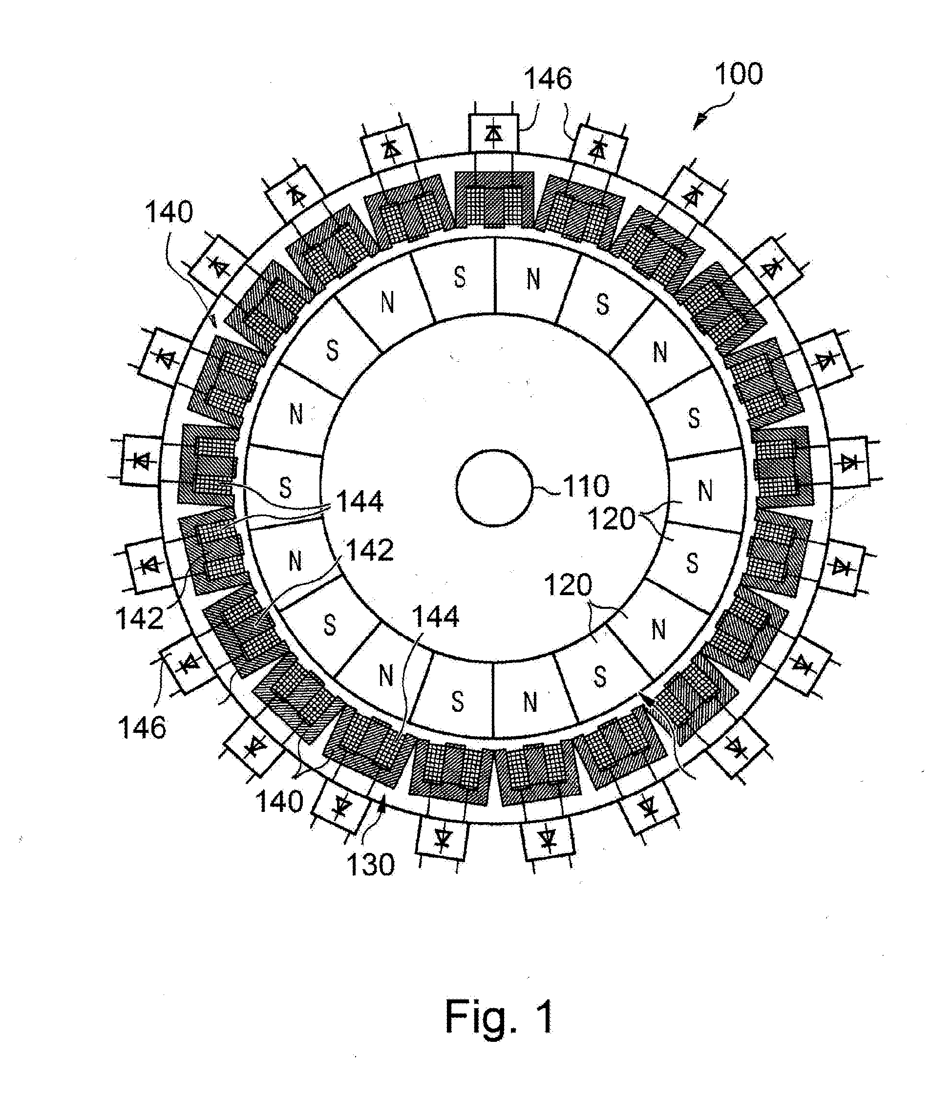
[0030]Referring first to FIG. 1, a prior art wind turbine generator is generally shown at 100. The generator 100 comprises a ring-shaped rotor 110 (also called rotor assembly) mounted for rotation around an axis of rotation within a coaxial ring-shaped stator 130 (also called stator assembly).

[0031]The rotor 110, which is directly or indirectly (e.g. through a transmission) coupled to the wind turbine (or a rotating assembly, not shown) comprises an even number of permanent magnets 120. As shown in FIG. 1, the magnets are mounted at the periphery of the ro...


PUM


Abstract

A magnetic voltage / current limiting system is mounted in conjunction with a main coil, in a coil assembly of a wind turbine generator, for limiting the outputted voltage (or current) to a predetermined upper value. The limiting system generally comprises at least one limiting coil and a control circuit connected to the main coil. The limiting system is configured to be activated when the voltage (or current) outputted by the main coil increases beyond the predetermined upper value. Once activated, the limiting system diverts a portion of the outputted current to the limiting coil such as to generate a magnetic field in the limiting coil. This additional magnetic field generally limits the amount magnetic field generated by passing magnets to flow through the main coil, thereby limiting the outputted voltage.

Description

CROSS-REFERENCE TO RELATED APPLICATIONS[0001]The present patent application claims the benefits of priority of U.S. Provisional Patent Application No. 61 / 902,365, entitled “Magnetostatic Voltage / Current Limiting System for Wind Turbine Generator and Generator Comprising the Same”, and filed at the United States Patent and Trademark Office on Nov. 11, 2013, the content of which is incorporated herein by reference.FIELD OF THE INVENTION[0002]The present invention generally relates to generators used with wind turbines for generating electric power from wind power, and more particularly to control circuits and systems for controlling the voltage and / or current generated by the generator. The present invention further relates to control circuits and systems for limiting the rotation speed of generators.BACKGROUND OF THE INVENTION[0003]Wind power is increasingly harvested as a source of renewable power. Typically, wind power is converted into electricity by rotating blades which, in turn...

Claims


Application Information

Patent Timeline
Patent Type & Authority Applications(United States)
IPC IPC(8): H02K11/00
CPCH02K11/0052H02K11/0057H02K11/26H02K11/27Y02E10/72
Inventor BEAULIEU, ANDRE
Owner BEAULIEU ANDRE
Why Eureka
Try Eureka