Energy-self-sufficient multiturn rotary encoder and method for determining a unique position of an encoder shaft by means of the multiturn rotary encoder

a multi-turn rotary encoder and encoder technology, applied in the field of multi-turn rotary encoders, can solve the problems of only allowing limited rotational speeds, high cost of rotary encoders, and wear of speed-reducing gear systems,

Active Publication Date: 2015-05-14
FRITZ KUEBLER ZAHL & SENSORTECHN
View PDF8 Cites 35 Cited by
  • Summary
  • Abstract
  • Description
  • Claims
  • Application Information

AI Technical Summary

Benefits of technology

[0027]In accordance with a preferred embodiment the pulse sensor comprises a, preferably one single, pulse wire and a, preferably one single, coil surrounding the pulse wire, and wherein the step of evaluating the additional signal and correcting the revolution-counter values comprises: applying current to the coil for a short period of time so that the external magnetic field of the excitation magnet is superimposed by an additional magnetic field and thereby a test-remagnetization pulse can be generated in the pulse wire which can be meas

Problems solved by technology

This type of rotary encoders can only be installed at high costs.
The speed-reducing gear system is subjected to wear and allows only limited rotational speeds.
Such an optical system is also not appropriate for specific tough cases of use when high mechanical impacts occur or climatic conditions are present which cause condensation.
However, during this time part of the energy generated by the so-called Wiegand-pulse is lost, for example, in terms of leakage currents.
However, this system does not deliver an absolute position when turned on for the first time.
However, one drawback of this system is that on the one hand a battery for buffering the data is required while an external supply voltage is turned off.
On the other hand relatively huge sensoric efforts, in terms of three Wiegand sensors, are a drawback.
A circuitry required for s

Method used


Image

  • Energy-self-sufficient multiturn rotary encoder and method for determining a unique position of an encoder shaft by means of the multiturn rotary encoder
  • Energy-self-sufficient multiturn rotary encoder and method for determining a unique position of an encoder shaft by means of the multiturn rotary encoder
  • Energy-self-sufficient multiturn rotary encoder and method for determining a unique position of an encoder shaft by means of the multiturn rotary encoder

Examples


Embodiment Construction

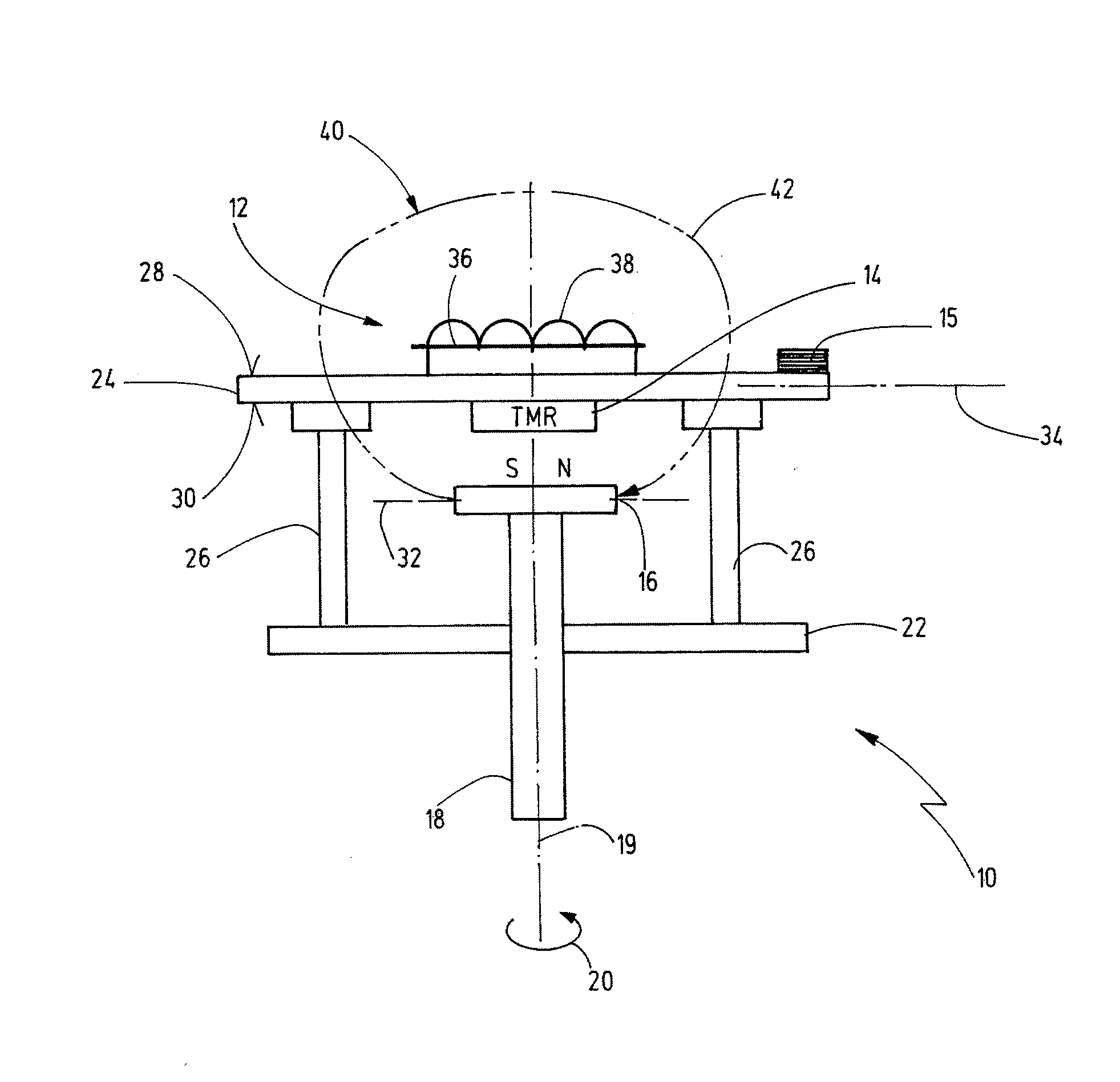
[0077]FIG. 1 shows a drastically simplified illustration of an MT rotary encoder 10. The MT rotary encoder 10 comprises a pulse-wire sensor 12 (e.g., a Wiegand wire sensor), a magnetic-field sensor (particularly an xMR element 14) and an evaluation logic, or evaluation unit 15. The mode of operation of the pulse-wire sensor 12, or a Wiegand wire sensor, is sufficiently known from the above-mentioned documents. In this context it is particularly referred to the document DE 34 08 478 C1.

[0078]The MT rotary encoder 10 cooperates with an excitation magnet 16 which is preferably a permanent magnet, in particular in terms of a dipole, being mounted in a rotationally fixed manner to an encoder shaft 18 for rotating together with the encoder shaft 18 about a rotational axis 19. The excitation magnet 16 and the encoder shaft 18 can rotate clockwise or counterclockwise. In FIG. 1 the encoder shaft 18 rotates counterclockwise as indicated by a rotational direction 20. The encoder shaft 18 belo...


PUM


Abstract

The present invention relates einen energy-self-sufficient multiturn rotary encoder for detecting a number of complete 360° revolutions of an encoder shaft, rotating about a rotational axis and to which an excitation magnet is mounted in a rotationally fixed manner for generating an external magnetic field, as well as for determining an absolute rotational angle indicating a fine-resolved position within one 360° revolution of the encoder shaft, wherein the multiturn rotary encoder for energy-self sufficiently detecting the number of the complete 360° revolutions of the encoder shaft several functional blocks comprises. Further, a corresponding method is taught.

Description

RELATED APPLICATIONS[0001]This is a continuation application of the co-pending international application PCT / EP2013 / 059043 (WO 2013 / 164361 A1) filed on Apr. 30, 2013, which claims the priorities of the German patent applications DE 10 2012 008 888.4 filed on Apr. 30, 2012, and DE 10 2012 017 071.8 filed on Apr. 30, 2012, all of which are incorporated fully herein by reference.BACKGROUND OF THE INVENTION[0002]The present invention relates to a multiturn rotary encoder (hereinafter also briefly designated as “MT rotary encoder”) for detecting both a fine-resolved position and a fine position (absolute angle within one 360° revolution), and a number of full, or complete, 360° revolutions (revolution counting). Additionally, the invention relates to a method for determining an unambiguous position of an encoder shaft, which rotates about a rotational axis, with an energy-self-sufficient multiturn rotary encoder configured to detect the number of completely passed 360° revolutions of the...

Claims


Application Information

Patent Timeline
IPC IPC(8): G01D5/16
CPCG01D5/16G01D5/145G01D5/3473G01D2205/26
Inventor GEHRINGER, STEPHANPALCZYNSKI, JURGENSTEINER, VIKTOR
Owner FRITZ KUEBLER ZAHL & SENSORTECHN
Why Eureka
Try Eureka