Flow rate timing apparatus
a timing apparatus and flow rate technology, applied in the field of flow rate measuring devices, can solve problems such as death, recurrent respiratory infections, health complications, and inability to meet the flow rate, and achieve the effects of reducing the risk of respiratory infection, and improving the accuracy of flow rate measuremen
- Summary
- Abstract
- Description
- Claims
- Application Information
AI Technical Summary
Benefits of technology
Problems solved by technology
Method used
Image
Examples
first embodiment
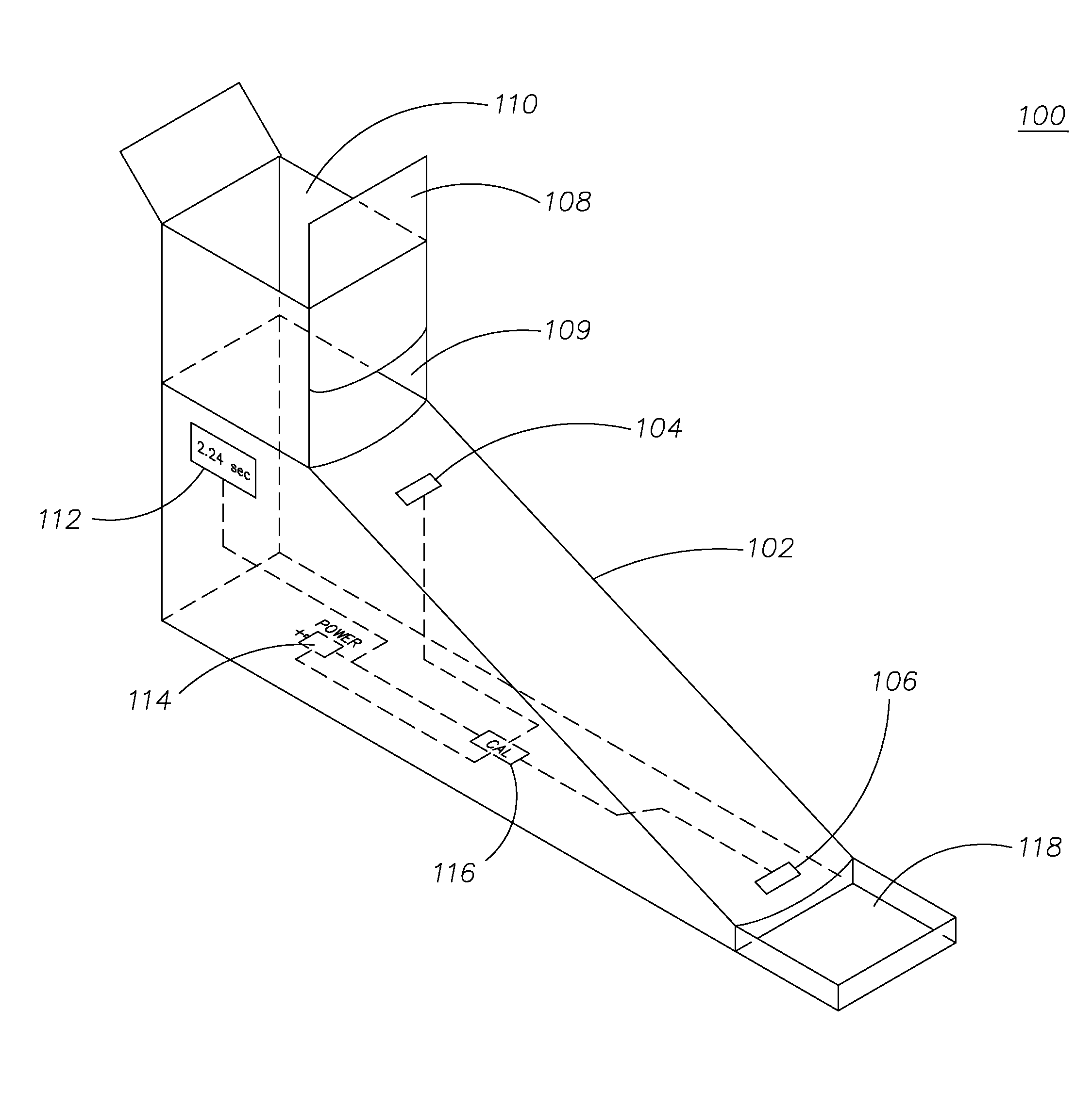
[0063]FIG. 3 illustrates a perspective view of a flow rate measuring device 100 configured in accordance with the present invention. The flow rate measuring device 100 has a ramp or chute 102 that includes a first liquid sensor 104 and a second liquid sensor 106. The liquid sensors 104, 106 are located in the lower floor or curved section of the chute 102. Preferably, the liquid sensors 104, 106 are covered with glass plates located within apertures in the chute 102, enabling the liquid sensors 104, 106 to optically detect liquid as it flows over the liquid sensor 104 and then the liquid sensor 106. The liquid sensors 104, 106 can be of a type disclosed in U.S. Pat. Nos. 3,558,898; 6,683,679; or 6,611,319, all of which are hereby incorporated by reference.
[0064]The upper portion of the chute 102 is connected to a reservoir or retention area 110. A vertical sliding gate 108 is formed into a wall of the retention area 110. The gate 108 can be slid up to create an opening 109 which all...
second embodiment
[0065]FIG. 4 illustrates another flow rate measuring device 200 configured in accordance with the present invention. The flow rate measuring device 200 is similar to a Bostwick consistometer with some additional improvements. A chute 202 is provided that can be constructed out of plastic or metal. The chute 202 includes a first liquid sensor 212 and a second liquid sensor 214, which may be similar to the liquid sensors 104, 106 discussed above. The first and second liquid sensors 212,214 are preferably photo detectors, photo sensors, optical detectors, optical sensors, or any type of sensor capable of detecting presence or absence / decrease of light. Additionally, if the first and second liquid sensors are a type of light sensor, the detected light can be from, and is not limited to, any particular spectrum of light. For example, the sensors 212,214 could detect visible light, or ultraviolet light, or both. The liquid sensors 212, 214 are preferably flush with the surface of the chut...
third embodiment
[0068]Turning now to the present invention, FIGS. 5 and 6 illustrate a flow rate measuring device 300 configured in accordance with the present invention. FIG. 5 is a perspective view of the measuring device 300 from the same elevation, and FIG. 6 is a perspective view of the measuring device 300 looking down from a higher elevation. The flow rate measuring device 300 includes a housing 301 having a body 302 and a cover plate 304 on a front 305 of the body 302. An input port 306 for inputting and testing flowable food is located at a top 307 of the device 300, and a catch tray 308 is located at a bottom 309 of the device 300. Legs 310 and 312 are attached to the bottom 309 of the device 300 in order to stabilize the device 300. The legs 310 and 312 fit into slots 314 and 316 on the bottom 309 of the device 300.
[0069]A tip cup 318 is pivotally mounted to the upper portion 319 of the device 300. Flowable food to be tested by the device 300 initially can be placed within the tip cup 31...
PUM
 Abstract
Description
Claims
Application Information
 - R&D
- Intellectual Property
- Life Sciences
- Materials
- Tech Scout
- Unparalleled Data Quality
- Higher Quality Content
- 60% Fewer Hallucinations
Browse by: Latest US Patents, China's latest patents, Technical Efficacy Thesaurus, Application Domain, Technology Topic, Popular Technical Reports.
© 2025 PatSnap. All rights reserved.Legal|Privacy policy|Modern Slavery Act Transparency Statement|Sitemap|About US| Contact US: help@patsnap.com


