

Method for quantification of process non-uniformity using model-based metrology
- Summary
- Abstract
- Description
- Claims
- Application Information
AI Technical Summary
Benefits of technology
Problems solved by technology
Method used
Image

Examples
Embodiment Construction
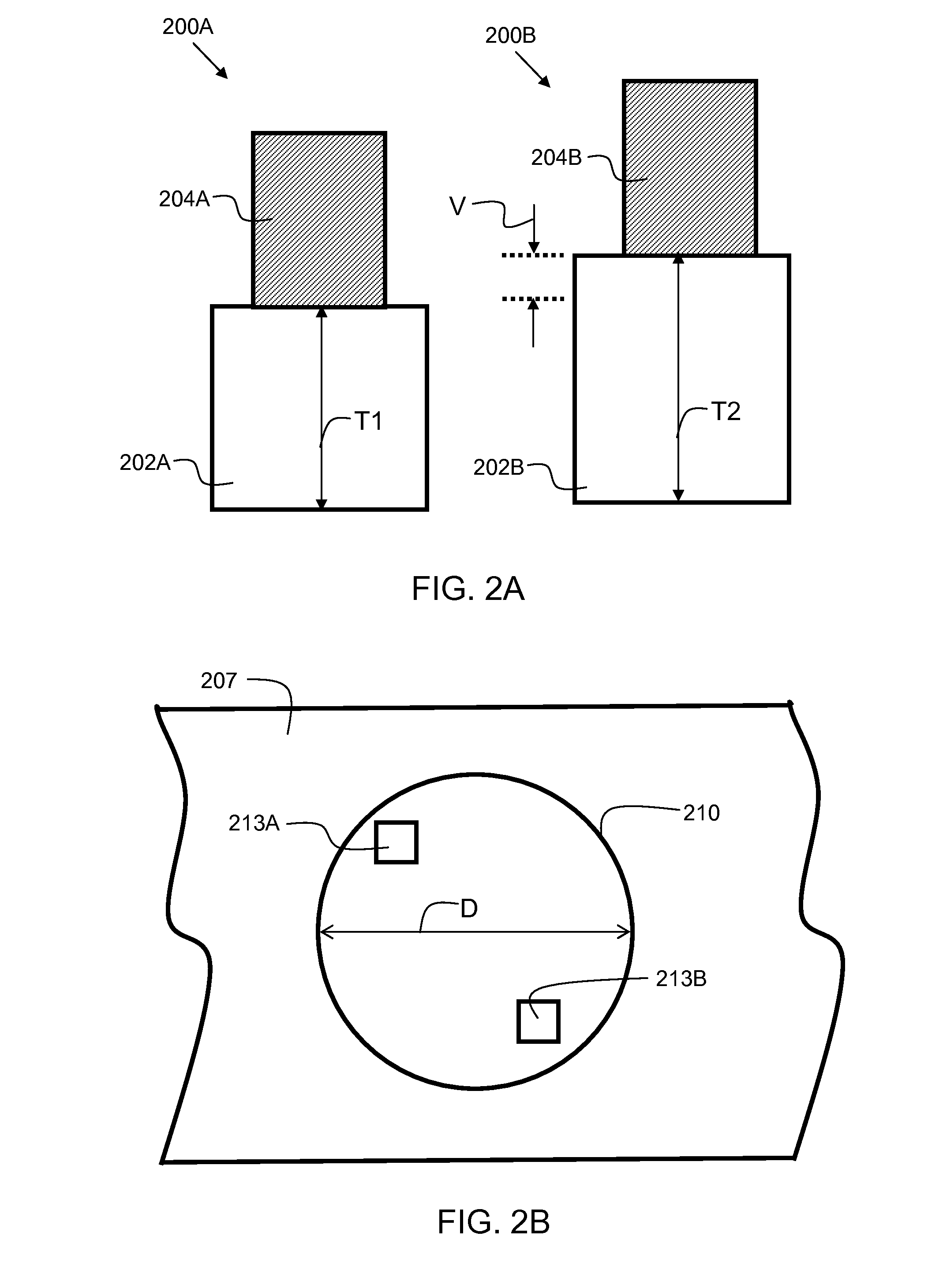
[0014]Embodiments of the present invention provide an improved method and system for assessing non-uniformity of features in the measurement area (within the beam spot) on a semiconductor structure, (e.g. wafer), such as a non-uniform film thickness. The scattering from non-uniform features is modeled. Post-processing the residual of theoretical and collected spectra is performed to assess a measure of non-uniformity from within an incident spot beam of a spectrum acquisition tool. Non-periodic topology differences have previously not been well accounted for in models. Embodiments of the present invention enable improved modeling for this type of manufacturing issue.
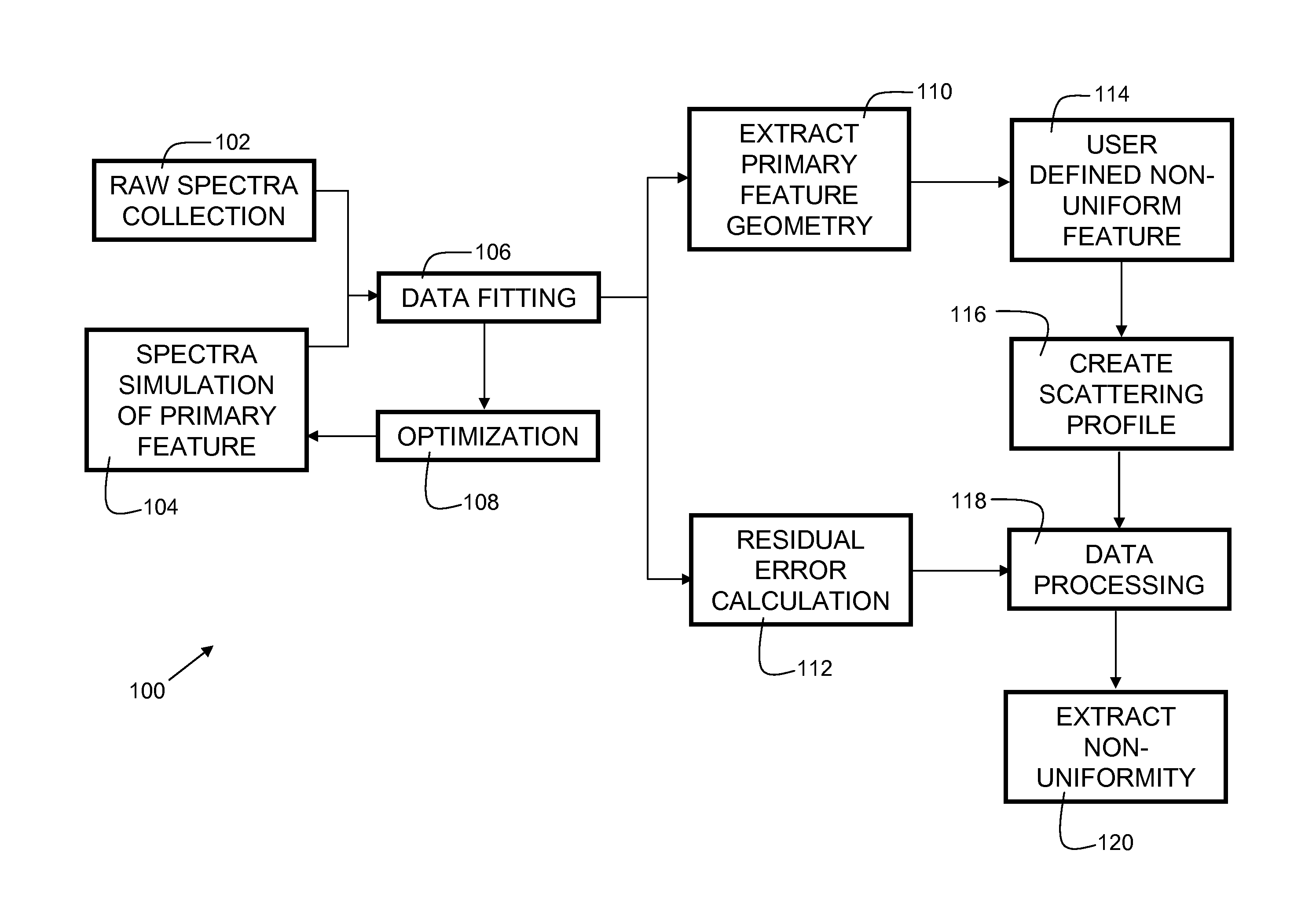
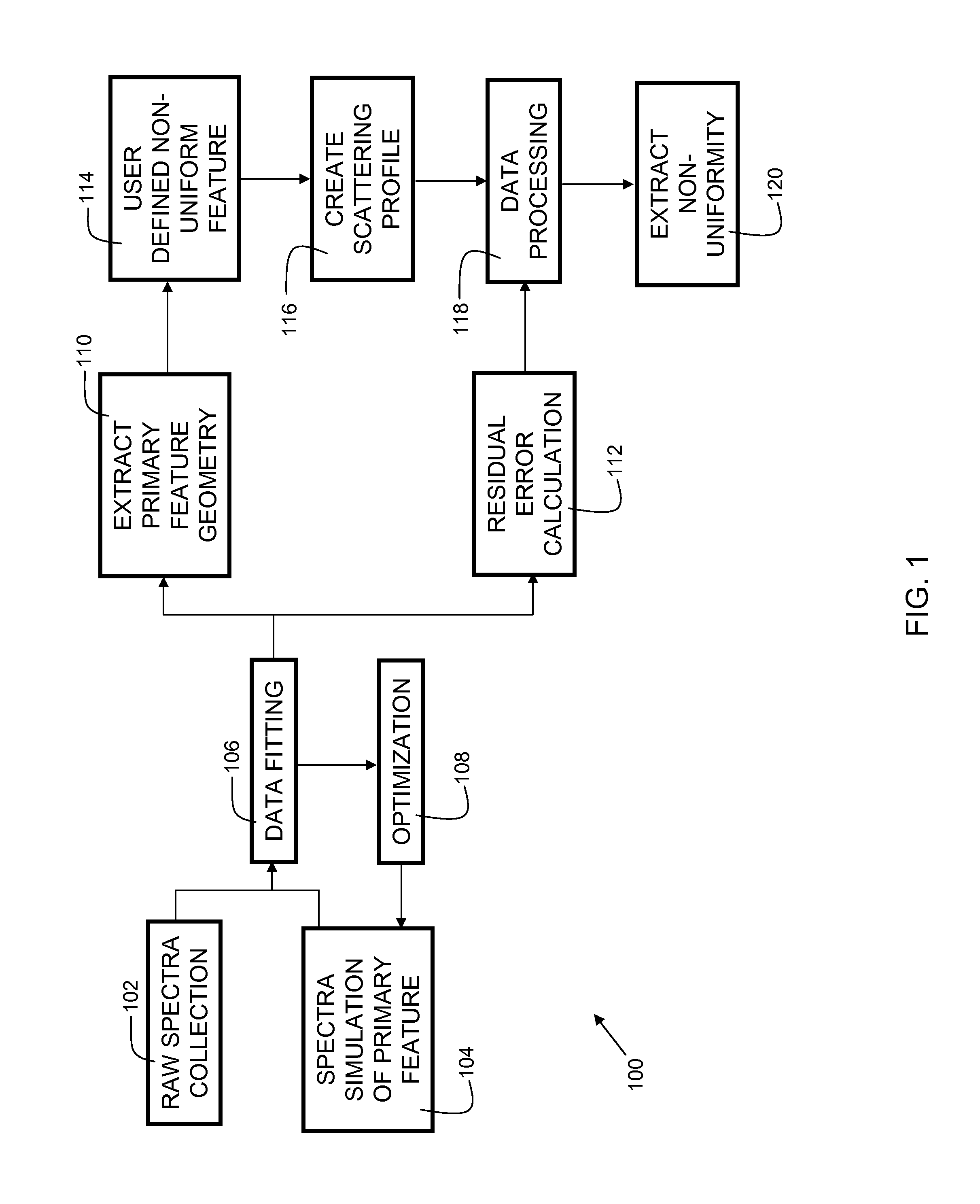
[0015]FIG. 1 is a flowchart 100 indicating process steps for embodiments of the present invention. In process step 102, raw (unprocessed) electromagnetic spectra are collected from physical samples. In embodiments, the raw spectra are acquired with a spectrum acquisition tool, such as a reflectometer tool or ellipsometer...
PUM
 Abstract
Description
Claims
Application Information