Percussion Unit

a percussion mechanism and unit technology, applied in the field of percussion mechanism units, can solve the problems of unreliable return movement of the striker, altering tolerances between components, and expanding components, and achieve the effects of ensuring the optimal operation of the percussion mechanism, reducing acceleration, driving force and/or vibration, and limiting the electric current consumption of the motor

Active Publication Date: 2015-05-21
ROBERT BOSCH GMBH
View PDF61 Cites 20 Cited by
  • Summary
  • Abstract
  • Description
  • Claims
  • Application Information

AI Technical Summary

Benefits of technology

[0015]Further, it is proposed that the control unit be provided, in at least one operating state, to set the operating parameter directly to the working value, for the purpose of changing from the idling operating state to the percussive operating state. The control unit can be provided, in particular, to set the operating parameter directly to the working value if a user specifies a working value that is a stable operating parameter under given conditions. With this working value, changing from the idling operating state to the percussive operating state can be effected in a reliable manner. Setting of a starting value can be avoided. Brief changing of the operating parameter for the purpose of starting the percussion mechanism, resulting in user irritation, can be avoided. There is no need for the control unit to intervene in the operating parameter.
[0016]Further, an operation change sensor is proposed, which is provided to signal a change of the operating mode. In particular, a change from the idling mode to the percussion mode can be signaled to the control unit by the operation change sensor. The operation change sensor can be provided to detect a contact pressure of the tool upon a workpiece. Advantageously, it can be identified when the user commences a working operation. Particularly advantageously, the operation change sensor can detect a switchover of the percussion mechanism, in particular opening and/or closing of idling openings, and of further openings, of the percussion mechanism that are provided for a change of operating mode. The operation change sensor can detect a displacement of a control sleeve provided for changing the operating mode of the percussion mechanism. The control unit can identify, advantageously, when a change of operating mode of the percussion mechanism occurs. Advantageously, the control unit can alter the operating paramet...

Problems solved by technology

The temperature can cause expansion of components, and alter tolerances between components.
In particular, a return movement of the striker can be unreli...

Method used


Image

  • Percussion Unit
  • Percussion Unit
  • Percussion Unit

Examples


Embodiment Construction

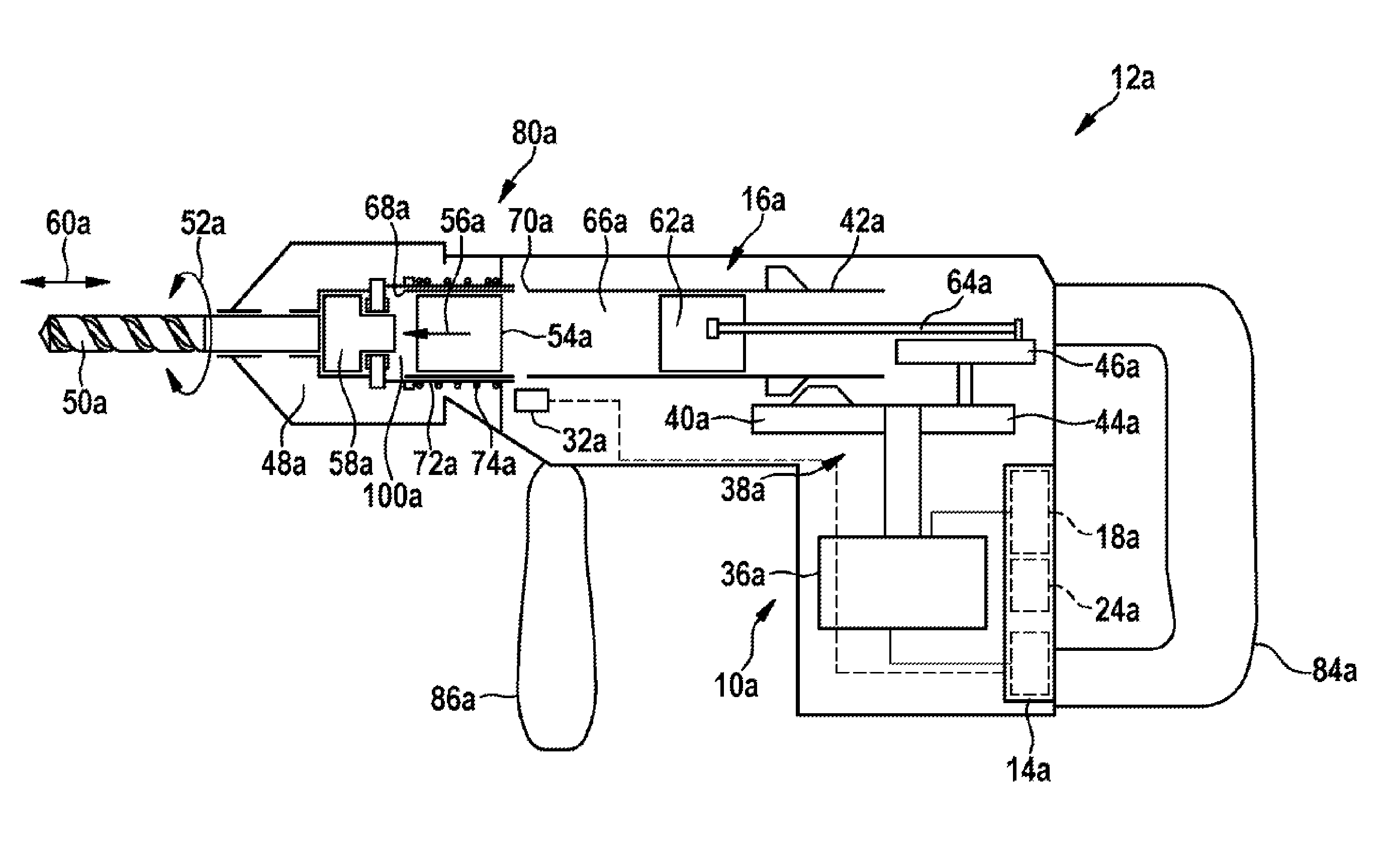
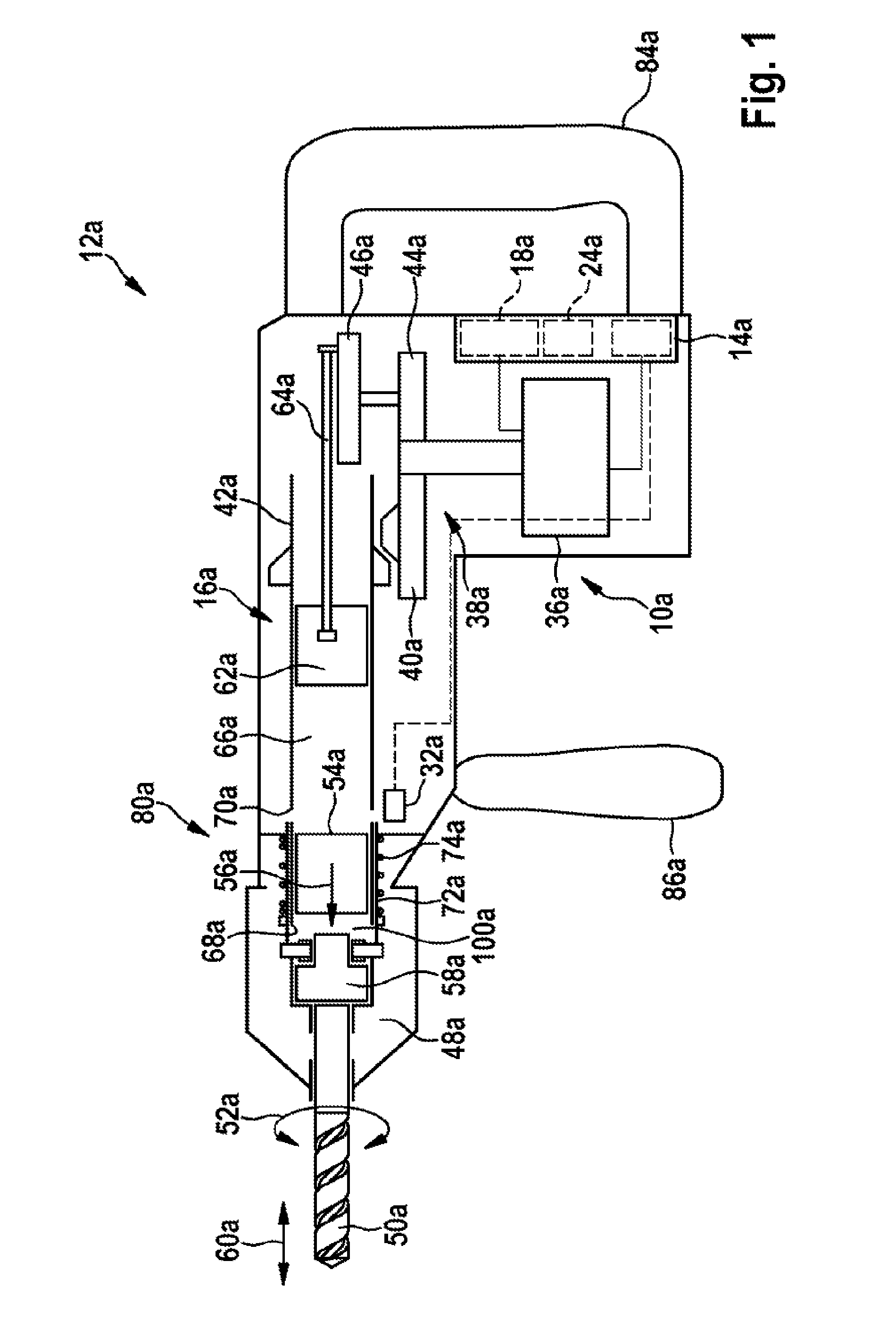
[0035]FIG. 1 and FIG. 2 show a rotary and percussion hammer 12a, having a percussion mechanism unit 10a, and having a control unit 14a, which is provided to control a pneumatic percussion mechanism 16a by open-loop and closed-loop control. The percussion mechanism unit 10a comprises a motor 36a, having a transmission unit 38a that drives a hammer tube 42a in rotation via a first gear wheel 40a and drives an eccentric gear mechanism 46a via a second gear wheel 44a. The hammer tube 42a is connected in a rotationally fixed manner to a tool holder 48a, in which a tool 50a can be clamped. For a drilling operation, the tool holder 48a and the tool 50a can be driven with a rotary working motion 52a, via the hammer tube 42a. If, in a percussive operating state, a striker 54a is accelerated in a percussion direction 56a, in the direction of the tool holder 48a, upon impacting upon a striking pin 58a that is disposed between the striker 54a and the tool 50a it exerts a percussive impulse that...


PUM


Abstract

Percussion unit, especially for a rotary hammer and/or percussion hammer, comprising a control unit which is designed for open-loop and/or closed loop control of a pneumatic percussion mechanism, and at least one operating condition sensor unit. According to the disclosure, the control unit is designed to detect at least one percussion mechanism parameter depending on measurement values of the operating condition sensor unit.

Description

PRIOR ART[0001]There are already known percussion mechanism units, in particular for a rotary and / or percussion hammer, comprising a control unit that is provided to control a pneumatic percussion mechanism, and comprising at least one operating-condition sensor unit.DISCLOSURE OF THE INVENTION[0002]The invention is based on a percussion mechanism unit, in particular for a rotary and / or percussion hammer, comprising a control unit that is provided to control a pneumatic percussion mechanism by open-loop and / or closed-loop control, and comprising at least one operating-condition sensor unit.[0003]It is proposed that the control unit be provided to determine at least one percussion-mechanism parameter in dependence on measurement values of the operating-condition sensor unit. “Provided” is to be understood to mean, in particular, specially designed and / or specially equipped. A “percussion mechanism unit” in this context is to be understood to mean, in particular, a unit provided to op...

Claims


Application Information

Patent Timeline
IPC IPC(8): B25D16/00B25D11/00
CPCB25D11/00B25D16/006B25D11/005B25D2211/003B25D2211/068B25D2250/035B25D2250/131B25D2250/145B25D2250/201B25D2250/221
Inventor NITSCHE, RAINERTAUBER, MATTHIASSCHLESAK, GERDVANDAMME, ANTOINEWINKLER, THOMASBERTSCH, CHRISTIANDUESSELBERG, ACHIMHOFFMANN, ULLIHENKE, THILOLENNARTZ, JUERGENSPRENGER, HELGE
Owner ROBERT BOSCH GMBH
Why Eureka
Try Eureka