Flip type case for portable electronic device

a protection case and electronic device technology, applied in the direction of electrical equipment, substation equipment, telephone set construction, etc., can solve the problems of inconvenient use of the protection case, the front cover part cannot be bent corresponding to the perimeter portion of the rear face of the electronic device, etc., to achieve smooth curved curve, good grip feeling, and elasticity and flexibility

Inactive Publication Date: 2015-05-21
SAMYANG CNS
View PDF6 Cites 42 Cited by
  • Summary
  • Abstract
  • Description
  • Claims
  • Application Information

AI Technical Summary

Benefits of technology

[0015]According to the present invention having the above-described configuration, since the core material (430) of the protection case is formed of the rubber or thermoplastic elastomer and thus has the elasticity and flexibility, the rear cover part (100) and front cover part (300) with the core embedded therein has the elasticity and flexibility. Therefore, when using the portable electronic device, the rear cover part (100) and the front cover part (300) are smoothly curved by a force applied by the hand, and thus end portions of the two cover parts do not cause soreness to the hand and a good grip feeling is provided.
[0016]In particular, when the see-through window (320) is to be formed in the front cover part (300), the core material (430) is formed of the transparent thermoplastic elastomer and the opening portions (412, 422) are formed in the skins (410, 420), and thus the opening portions (412, 422) are covere

Problems solved by technology

Therefore, when the cellular phone is used, an end portion of the front cover part (10) presses user's palm or fingers and thus the hand is sore, which makes the use of the protection case inconvenient.
In general, a perimeter portion of the rear face of most of the electronic devices including the smart phone is curved for the electronic devices to be convenient to be held and

Method used


Image

  • Flip type case for portable electronic device
  • Flip type case for portable electronic device
  • Flip type case for portable electronic device

Examples


first embodiment

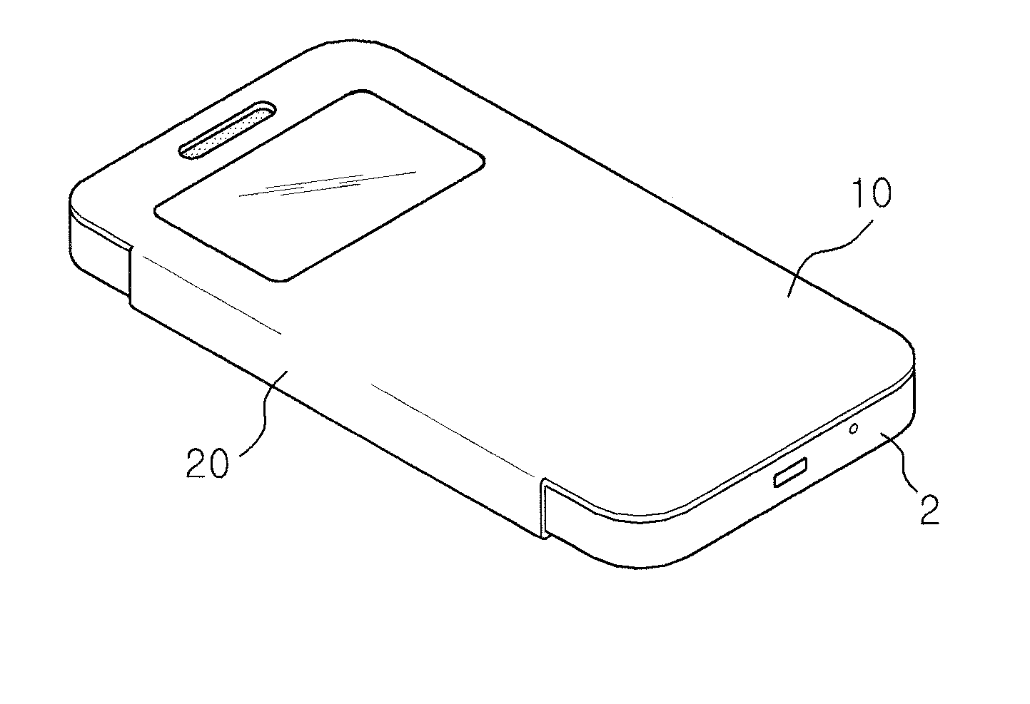
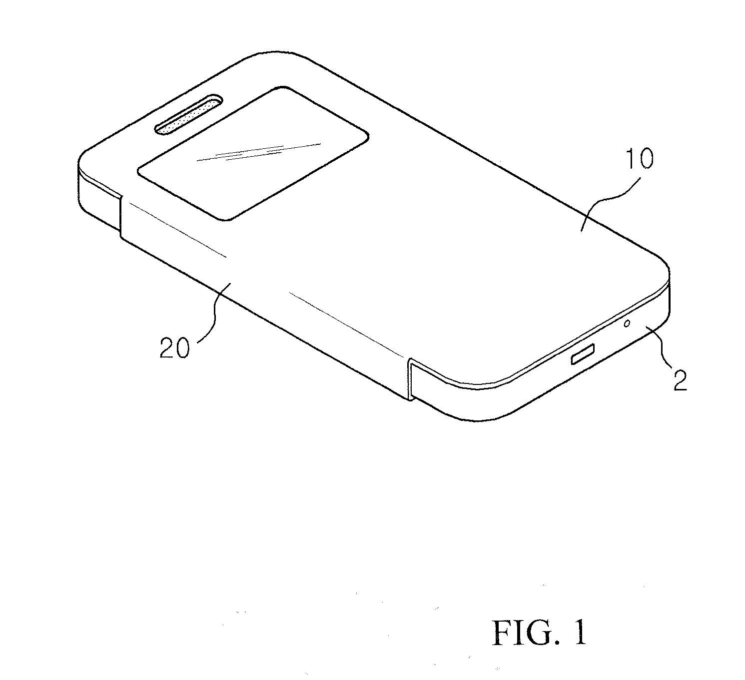
[0027]FIGS. 3 and 4 are perspective view illustrating the present invention, and cross-sectional view illustrating a used state thereof, respectively. As illustrated, the present invention includes a rear cover part (100) covering a rear face of a smart phone (2); and a front cover part (300) connected to one side of the rear cover part (100) by a connection part (200) and covering a front face of the smart phone (2).

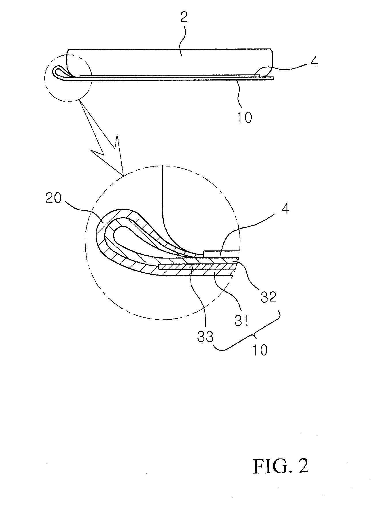
[0028]These rear cover part (100), connection part (200) and front cover part (300) are formed by a pair of skins (410, 420) laminated one above the other, wherein the skins (410, 420) consist of natural leather or synthetic leather. Thus, the rear cover part (100), connection part (200) and front cover part (300) have flexibility.

[0029]Meanwhile, a core material (430) is embedded in the rear cover part (100) and the front cover part (300). The core material (430) is formed of rubber or thermoplastic elastomer and is preferably extruded as a sheet having a thickness of ...

second embodiment

[0036]FIGS. 5 and 6 shows the present invention, wherein a see-through window (320) for viewing a crystal screen of the smart phone is formed in the front cover part (300).

[0037]In the second embodiment, opening portions (412, 422) are formed in the skins (410, 412) which form the front cover part (300), and a see-through window member (450) is further provided for covering the opening portions (412, 422). The see-through window member (450) is made of transparent hard synthetic resin sheet such as PC; as illustrated in FIG. 6, the see-through window member (450) is formed with a size corresponding to the opening portions (412, 422), and the core material (430) is double injection molded on a perimeter portion of the see-through window member (450).

[0038]Preferably, as illustrated, protrusions (452) are formed on the perimeter portion of the see-through window member (450). These protrusions (452) enhances a strength of coupling between the core material (430) and the see-through wi...

third embodiment

[0040]FIGS. 7 shows the present invention, wherein, unlike the previous embodiment, the separate see-through window member (450) is not used and the see-through window (320) is formed by the core material (430).

[0041]In the third embodiment, the core material (430) is formed of transparent thermoplastic elastomer and the core material (430) is exposed to the outside through the opening portions (412, 422) of the skins (410, 420), thereby forming the see-through window (320). Since the see-through window (320) is formed by the core material (430) like this, it is preferred that the core material (430) is formed of thermoplastic elastomer having a high transparency.

[0042]For this purpose, in the third embodiment, the core material (430) is formed by extruding thermoplastic elastomer consisting of polybutylene adipate with number-average molecular weight of 600 to 2500, polyhexylene adipate with number-average molecular weight of 600 to 2500, 1,2-ethylene glycol, 1,4-butanediol, 1,6-he...


PUM


Abstract

A flip-type protection case for portable electronic device of the present invention has a flexibility and thus provides improved grip feeling, and end portions of the protection case do not cause soreness to a hand and thus the protection case is convenient is to be used. The flip-type protection case for portable electronic device of the present invention includes a rear cover part (100) covering a rear face of the portable electronic device; and a front cover part (300) connected to the rear cover part (100) by a connection part (200) and covering a front face of the portable electronic device, wherein a core material (430) is embedded between a pair of skins (410, 420) at least in the front cover part (300) of the rear cover part (100) and the front cover part (300), and wherein the core material (430) is a sheet formed of rubber or thermoplastic elastomer.

Description

TECHNICAL FIELD[0001]The invention relates to a flip-type protection case for portable electronic device, and more particularly, to a flip-type protection case for portable electronic device having a novel configuration wherein a grip feeling is improved and thus the protection case is convenient to use.BACKGROUND ART[0002]Use of various mobile electronic devices such as cellular phone, tablet PC etc. is prevalent, and the mobile electronic devices are commonly used while being covered by a separate protection case for protecting the mobile electronic devices from a shock to prevent occurrence of scratch on a surface thereof.[0003]FIG. 1 shows that the cellar phone is covered by a flip-type protection case. As illustrated in the figure, the flip-type protection case consists of a flip for covering a front face of the cellar phone, i.e., a front cover part (10), and a connection part (20) extending from one side of the front cover part (10) and releasably coupled with a battery cover...

Claims


Application Information

Patent Timeline
IPC IPC(8): H04B1/3888H04M1/02
CPCH04M1/0202H04B1/3888H04M1/0214H04M1/185A45C11/00A45C13/002A45C2011/002A45C2200/10
Inventor KIM, SUNG JUN
Owner SAMYANG CNS
Why Eureka
Try Eureka